Nissan March K13. Manual - part 456


  Index      Nissan     Nissan March K13 - Service and Repair Manual)


Search            


Content   ..  454  455  456  457   ..


Nissan March K13. Manual - part 456


MA-30

< SERVICE DATA AND SPECIFICATIONS (SDS) 

SERVICE DATA AND SPECIFICATIONS (SDS)

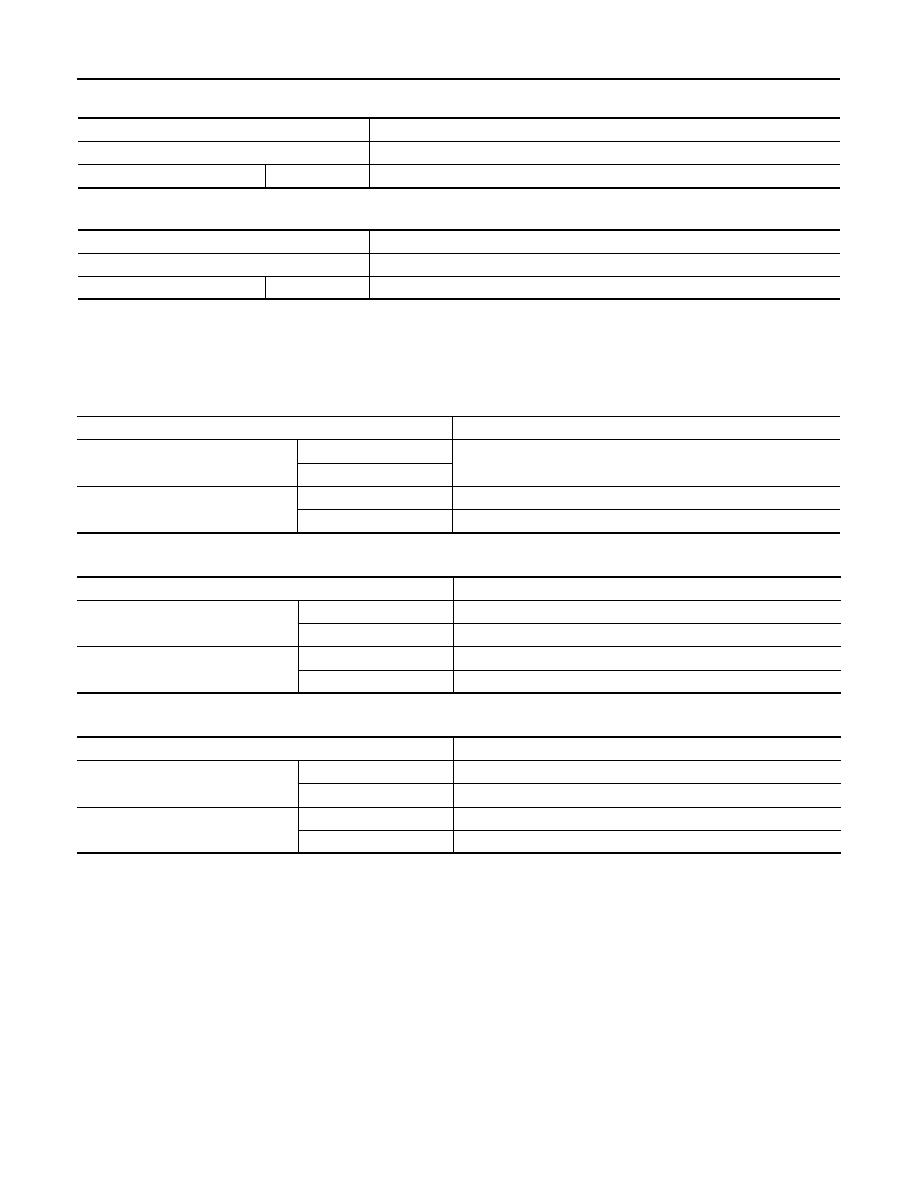
With EGR control valve

Unit: mm (in)

Without EGR control valve

Unit: mm (in)

ROAD WHEEL

ROAD WHEEL : Road Wheel

INFOID:0000000006069240

ALUMINUM WHEEL 

STEEL WHEEL

STEEL WHEEL (FOR EMERGENCY USE)

Make

DENSO

Standard type

FXE20MR11

Spark plug gap

Standard

1.1 (0.043)

Make

FEDEMO

Standard type

REA12MC4

Spark plug gap

Standard

1.1 (0.043)

Item

Limit

Radial runout

Lateral deflection

Less than 0.3 mm (0.012 in)

Vertical deflection

Allowable unbalance

Dynamic (At flange)

Less than 10 g (0.35 oz) (one side)

Static (At flange)

Less than 20 g (0.70 oz)

Item

Limit

Radial runout

Lateral deflection

Less than 0.8 mm (0.031 in)

Vertical deflection

Less than 0.5 mm (0.020 in)

Allowable unbalance

Dynamic (At flange)

Less than 10 g (0.35 oz) (one side)

Static (At flange)

Less than 20 g (0.70 oz)

Item

Limit

Radial runout

Lateral deflection

Less than 0.8 mm (0.031 in)

Vertical deflection

Less than 0.5 mm (0.020 in)

Allowable unbalance

Dynamic (At flange)

Less than 10 g (0.35 oz) (one side)

Static (At flange)

Less than 20 g (0.70 oz)

MIR-1

DRIVER CONTROLS

C

D

E

F

G

H

I

J

K

M

SECTION 

MIR

A

B

MIR

N

O

P

CONTENTS

MIRRORS

PRECAUTION ...............................................

3

PRECAUTIONS ...................................................

3

Precaution for Supplemental Restraint System 
(SRS) "AIR BAG" and "SEAT BELT PRE-TEN-
SIONER" .................................................................
..

3

Precaution Necessary for Steering Wheel Rota-
tion after Battery Disconnect  ...................................
..

3

PREPARATION ............................................

5

PREPARATION ...................................................

5

Commercial Service Tools .......................................

5

SYSTEM DESCRIPTION  ..............................

6

COMPONENT PARTS  ........................................

6

DOOR MIRROR SYSTEM  ...........................................

6

DOOR MIRROR SYSTEM : Component Descrip-
tion ..........................................................................
..

6

AUTO RETRACTABLE DOOR MIRROR SYSTEM 

......

6

AUTO RETRACTABLE DOOR MIRROR SYS-
TEM : Component Parts Location  ...........................
..

6

AUTO RETRACTABLE DOOR MIRROR SYS-
TEM : Component Description  ................................
..

7

SYSTEM ..............................................................

8

AUTO RETRACTABLE DOOR MIRROR SYSTEM 

......

8

AUTO RETRACTABLE DOOR MIRROR SYS-
TEM : System Diagram  ...........................................
..

8

AUTO RETRACTABLE DOOR MIRROR SYS-
TEM : System Description .......................................
..

8

DIAGNOSIS SYSTEM (BCM)  .............................

9

COMMON ITEM  ...........................................................

9

COMMON ITEM : CONSULT-III Function (BCM - 
COMMON ITEM) .....................................................
..

9

INTELLIGENT KEY  ...................................................

10

INTELLIGENT KEY : CONSULT-III Function 
(BCM - INTELLIGENT KEY) ....................................

10

ECU DIAGNOSIS INFORMATION ..............

14

BCM (BODY CONTROL MODULE)  .................

14

List of ECU Reference .............................................

14

WIRING DIAGRAM  ......................................

15

DOOR MIRROR SYSTEM .................................

15

Wiring Diagram ........................................................

15

BASIC INSPECTION  ...................................

16

DIAGNOSIS AND REPAIR WORK FLOW  .......

16

Work Flow ................................................................

16

DTC/CIRCUIT DIAGNOSIS  .........................

17

DOOR MIRROR REMOTE CONTROL 
SWITCH (MIRROR SWITCH/CHANGEOVER 
SWITCH) ...........................................................

17

Component Inspection .............................................

17

DOOR MIRROR REMOTE CONTROL 
SWITCH (OPEN/CLOSE SWITCH)  ..................

18

Component Inspection .............................................

18

POWER SUPPLY AND GROUND CIRCUIT  ....

19

DOOR MIRROR REMOTE CONTROL SWITCH 
(OPEN/CLOSE SWITCH)  ..........................................

19

DOOR MIRROR REMOTE CONTROL SWITCH 
(OPEN/CLOSE SWITCH) : Diagnosis Procedure ....

19

AUTO RETRACTABLE DOOR MIRROR CIR-
CUIT ..................................................................

20

Component Function Check  ....................................

20

Diagnosis Procedure  ...............................................

20

Component Inspection .............................................

21

DOOR MIRROR (OPEN/CLOSE MOTOR)  .......

22

MIR-2

Component Function Check .................................

22

Diagnosis Procedure  ..............................................

22

Component Inspection ............................................

23

SYMPTOM DIAGNOSIS  .............................

25

ELECTRIC FOLDABLE DOOR MIRROR 
DOES NOT OPERATE  ......................................

25

Diagnosis Procedure  ..............................................

25

AUTO RETRACTABLE DOOR MIRROR 
DOES NOT OPERATE  ......................................

26

Diagnosis Procedure  ..............................................

26

SQUEAK AND RATTLE TROUBLE DIAG-
NOSES ...............................................................

27

Work Flow ...............................................................

27

Inspection Procedure ..............................................

29

Diagnostic Worksheet .............................................

31

REMOVAL AND INSTALLATION ...............

33

INSIDE MIRROR ................................................

33

Exploded View  ........................................................

33

Removal and Installation .........................................

33

OUTSIDE MIRROR ............................................

35

Exploded View  ........................................................

35

DOOR MIRROR ASSEMBLY ....................................

35

DOOR MIRROR ASSEMBLY : Removal and In-
stallation ..................................................................

35

GLASS MIRROR  .......................................................

36

GLASS MIRROR : Disassembly and Assembly  .....

36

DOOR MIRROR COVER  ...........................................

37

DOOR MIRROR COVER : Disassembly and As-
sembly .....................................................................

37

DOOR MIRROR REMOTE CONTROL 
SWITCH .............................................................

38

Removal and Installation .........................................

38

PRECAUTIONS

MIR-3

< PRECAUTION >

C

D

E

F

G

H

I

J

K

M

A

B

MIR

N

O

P

PRECAUTION

PRECAUTIONS

Precaution for Supplemental Restraint System (SRS) "AIR BAG" and "SEAT BELT 
PRE-TENSIONER"

INFOID:0000000006007910

The Supplemental Restraint System such as “AIR BAG” and “SEAT BELT PRE-TENSIONER”, used along
with a front seat belt, helps to reduce the risk or severity of injury to the driver and front passenger for certain
types of collision. This system includes seat belt switch inputs and dual stage front air bag modules. The SRS
system uses the seat belt switches to determine the front air bag deployment, and may only deploy one front
air bag, depending on the severity of a collision and whether the front occupants are belted or unbelted.
Information necessary to service the system safely is included in the “SRS AIR BAG” and “SEAT BELT” of this
Service Manual.

WARNING:

• To avoid rendering the SRS inoperative, which could increase the risk of personal injury or death in

the event of a collision that would result in air bag inflation, all maintenance must be performed by
an authorized NISSAN/INFINITI dealer.

• Improper maintenance, including incorrect removal and installation of the SRS, can lead to personal

injury caused by unintentional activation of the system. For removal of Spiral Cable and Air Bag
Module, see the “SRS AIR BAG”.

• Do not use electrical test equipment on any circuit related to the SRS unless instructed to in this

Service Manual. SRS wiring harnesses can be identified by yellow and/or orange harnesses or har-
ness connectors.

PRECAUTIONS WHEN USING POWER TOOLS (AIR OR ELECTRIC) AND HAMMERS

WARNING:

• When working near the Air Bag Diagnosis Sensor Unit or other Air Bag System sensors with the

ignition ON or engine running, DO NOT use air or electric power tools or strike near the sensor(s)
with a hammer. Heavy vibration could activate the sensor(s) and deploy the air bag(s), possibly
causing serious injury.

• When using air or electric power tools or hammers, always switch the ignition OFF, disconnect the

battery, and wait at least 3 minutes before performing any service.

Precaution Necessary for Steering Wheel Rotation after Battery Disconnect

INFOID:0000000006007911

NOTE:
• Before removing and installing any control units, first turn the push-button ignition switch to the LOCK posi-

tion, then disconnect both battery cables.

• After finishing work, confirm that all control unit connectors are connected properly, then re-connect both

battery cables.

• Always use CONSULT-III to perform self-diagnosis as a part of each function inspection after finishing work.

If a DTC is detected, perform trouble diagnosis according to self-diagnosis results.

For vehicle with steering lock unit, if the battery is disconnected or discharged, the steering wheel will lock and
cannot be turned.
If turning the steering wheel is required with the battery disconnected or discharged, follow the operation pro-
cedure below before starting the repair operation.

OPERATION PROCEDURE

1.

Connect both battery cables.
NOTE:
Supply power using jumper cables if battery is discharged.

2.

Turn the push-button ignition switch to ACC position.
(At this time, the steering lock will be released.)

3.

Disconnect both battery cables. The steering lock will remain released with both battery cables discon-
nected and the steering wheel can be turned.

4.

Perform the necessary repair operation.


Content   ..  454  455  456  457   ..