Nissan March K13. Manual - part 404


  Index      Nissan     Nissan March K13 - Service and Repair Manual)


Search            


Content   ..  402  403  404  405   ..


Nissan March K13. Manual - part 404


HAC-150

< REMOVAL AND INSTALLATION >

[HEATER AND VENTILATION]

DOOR CABLE

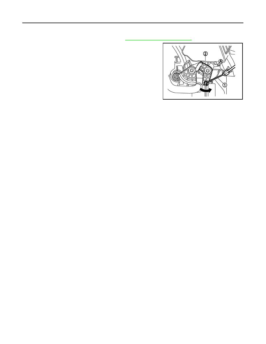
AIR MIX DOOR CABLE : Adjustment

INFOID:0000000006057686

1.

Remove instrument passenger cover. Refer to 

IP-13, "Removal and Installation"

.

2.

Disconnect air mix door cable (1) from clamp (A).

3.

Set temperature control dial to full cold position.

4.

Push air mix door link (2) in the direction shown by the arrow,
and then carefully pulling outer cable to A/C control side, and
connect clamp.

5.

Operate temperature control dial to insure that inner cable moves smoothly.

CAUTION:

When clamping the outer cable, never move the inner cable.

JMIIA0619ZZ

HRN-2

< PRECAUTION >

PRECAUTIONS

PRECAUTION

PRECAUTIONS

Precaution for Supplemental Restraint System (SRS) "AIR BAG" and "SEAT BELT 
PRE-TENSIONER"

INFOID:0000000005984311

The Supplemental Restraint System such as “AIR BAG” and “SEAT BELT PRE-TENSIONER”, used along
with a front seat belt, helps to reduce the risk or severity of injury to the driver and front passenger for certain
types of collision. Information necessary to service the system safely is included in the “SRS AIR BAG” and
“SEAT BELT” of this Service Manual.

WARNING:

• To avoid rendering the SRS inoperative, which could increase the risk of personal injury or death in

the event of a collision which would result in air bag inflation, all maintenance must be performed by
an authorized NISSAN/INFINITI dealer.

• Improper maintenance, including incorrect removal and installation of the SRS, can lead to personal

injury caused by unintentional activation of the system. For removal of Spiral Cable and Air Bag
Module, see the “SRS AIR BAG”.

• Do not use electrical test equipment on any circuit related to the SRS unless instructed to in this

Service Manual. SRS wiring harnesses can be identified by yellow and/or orange harnesses or har-
ness connectors.

PRECAUTIONS WHEN USING POWER TOOLS (AIR OR ELECTRIC) AND HAMMERS

WARNING:

• When working near the Air Bag Diagnosis Sensor Unit or other Air Bag System sensors with the

ignition ON or engine running, DO NOT use air or electric power tools or strike near the sensor(s)
with a hammer. Heavy vibration could activate the sensor(s) and deploy the air bag(s), possibly
causing serious injury.

• When using air or electric power tools or hammers, always switch the ignition OFF, disconnect the

battery, and wait at least 3 minutes before performing any service.

HORN

HRN-3

< WIRING DIAGRAM >

C

D

E

F

G

H

I

J

K

M

A

B

HRN

N

O

P

WIRING DIAGRAM

HORN

Wiring Diagram

INFOID:0000000005984309

For connector terminal arrangements, harness layouts, and alphabets in a 

 (option abbreviation; if not

described in wiring diagram), refer to 

GI-12, "Connector Information"

.

JCLWM3546GB


Content   ..  402  403  404  405   ..