Nissan March K13. Manual - part 403
HAC-146
< REMOVAL AND INSTALLATION >
[HEATER AND VENTILATION]
HEATER CONTROL
REMOVAL AND INSTALLATION
HEATER CONTROL
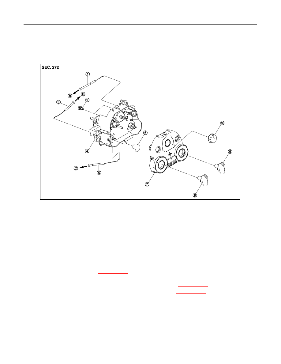
Exploded View
INFOID:0000000006024192
Removal and Installation
INFOID:0000000006024193
REMOVAL
1.
Remove A/C finisher. Refer to
XX-XX, "*****"
.
2.
Remove the heater control mounting screws.
3.
Remove the air mix door cable from the A/C unit assembly. Refer to
XX-XX, "*****"
.
4.
Remove the mode door cable from the A/C unit assembly. Refer to
XX-XX, "*****"
.
5.
Disconnect harness connector.
6.
Remove the A/C control.
INSTALLATION
Installation is basically the reverse order of removal.
1.
Air mix door cable (with heater mod-
els)
2.
Illumination bulb
3.
Mode door cable
4.
A/C control
5.
Intake door cable
6.
Knob
7.
A/C finisher
8.
Mode dial
9.
Temperature dial (with heater mod-
els)
10. Fan control dial
A.
To mode door link
B.
To air mix door link
C.
Intake door link
JMIIA0753ZZ