Nissan March K13. Manual - part 388


  Index      Nissan     Nissan March K13 - Service and Repair Manual)


Search            


Content   ..  386  387  388  389   ..


Nissan March K13. Manual - part 388


HAC-86

< SYSTEM DESCRIPTION >

[MANUAL AIR CONDITIONER]

COMPONENT PARTS

SYSTEM DESCRIPTION

COMPONENT PARTS

MANUAL AIR CONDITIONING SYSTEM

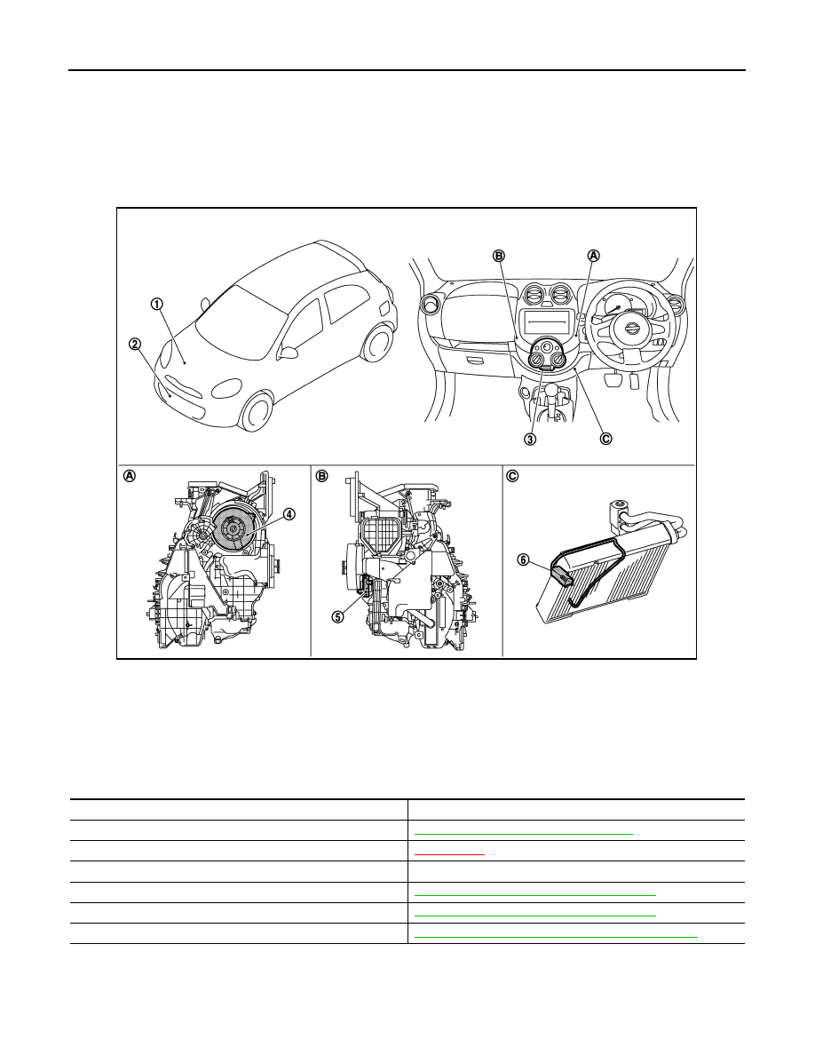
MANUAL AIR CONDITIONING SYSTEM : Component Part Location

INFOID:0000000006024104

MANUAL AIR CONDITIONING SYSTEM : Component Description

INFOID:0000000006024105

A/C UNIT ASSEMBLY

1.

Magnet clutch

2.

Refrigerant pressure sensor

3.

A/C control

4.

Blower motor

5.

Blower fan resistor

6.

Thermo control amp.

A.

Located in the right side of A/C unit 
assembly

B.

Located in the left side of A/C unit as-
sembly

C.

Located on evaporator

JMIIA0700ZZ

Component

Reference/Function

Magnet clutch

HAC-87, "COMPRESSOR : Magnet Clutch"

Refrigerant pressure sensor

XX-XX, "*****"


A/C control

Controls the air conditioner function.

Blower motor

HAC-87, "A/C UNIT ASSEMBLY : Blower Motor"

Blower fan resistor

HAC-87, "A/C UNIT ASSEMBLY : Blower Motor"

Thermo control amp.

HAC-87, "A/C UNIT ASSEMBLY : Thermo Control Amp."

COMPONENT PARTS

HAC-87

< SYSTEM DESCRIPTION >

[MANUAL AIR CONDITIONER]

C

D

E

F

G

H

J

K

L

M

A

B

HAC

N

O

P

A/C UNIT ASSEMBLY : Blower Fan Resistor

INFOID:0000000006043969

• Compact and lightweight resistor is adopted with outstanding venti-

lation. 

• Temperature fuse is installed to protects the blower motor circuit.

A/C UNIT ASSEMBLY : Blower Motor

INFOID:0000000006024119

• The blower motor (1) is installed in the RH side of A/C unit assem-

bly.

• The blower motor adopts the forcible air cooling system and one-

touch installation system without any screws.

A/C UNIT ASSEMBLY : Thermo Control Amp.

INFOID:0000000006024116

COMPONENT DESCRIPTION

• Thermo control amp. (1) is composed of thermistor and amplifier.

Thermistor is installed on evaporator, and amplifier is attached to
foot duct (left).

• When the thermistor detecting temperature which passing through

evaporator is extremely low, thermo control amp. sends the thermo
control amp. OFF signal to BCM, and stops the compressor.

OPERATING RATE CONTROL

• Thermo control amp. detects the positions of air temperature control dial and MODE dial.
• Thermo control amp. corrects the stopping temperature of A/C compressor depending on the condition of A/

C operation, and prevents too much heating by turning thermo control amp. ON 

 OFF.

COMPRESSOR

COMPRESSOR : Magnet Clutch

INFOID:0000000006024122

• The magnet clutch is the device that drives the compressor with the signal from IPDM E/R. 
• Compressor is driven by the magnet clutch which is charged magnetic force by electrified.
• IPDM E/R controls magnet clutch by turning the built in A/C relay to ON 

 OFF according to ECM request.

: Vehicle front

JMIIA0704ZZ

: Vehicle front

JMIIA0703ZZ

JPIIA1750ZZ

HAC-88

< SYSTEM DESCRIPTION >

[MANUAL AIR CONDITIONER]

SYSTEM

SYSTEM

System Diagram

INFOID:0000000006024106

System Description

INFOID:0000000006043972

• Manual air conditioner system is controlled by each function of BCM, ECM or IPDM E/R.

Control by BCM

- Compressor control

Control by ECM

- Compressor control
- Cooling fan control. Refer to  

XX-XX, "*****"

.

- Air conditioner cut control. Refer to 

XX-XX, "*****"

.

Control by IPDM E/R

- Relay control. Refer to 

XX-XX, "*****"

.

- Cooling fan control. Refer to 

XX-XX, "*****"

.

• Fan speed of blower fan motor is changed by the combination of fan switch operation and blower fan resistor

control.

Compressor Control

INFOID:0000000006043973

DESCRIPTION

• BCM transmits the A/C ON signal and blower fan ON signal to ECM via CAN communication line only when

the compressor operational condition is satisfied, and A/C indicator is turned ON.
NOTE:
Compressor operational condition
• Thermo control amp. signal ON
• Blower fan signal ON
• A/C switch signal ON

• ECM judges the conditions of each sensor (Refrigerant pressure sensor signal, accelerator position signal,

etc.), and transmits the A/C compressor request signal to IPDM E/R via CAN communication line.

• By receiving the A/C compressor request signal from ECM, IPDM E/R turns the A/C relay to ON, and acti-

vates the compressor.

JMIIA0701GB

SYSTEM

HAC-89

< SYSTEM DESCRIPTION >

[MANUAL AIR CONDITIONER]

C

D

E

F

G

H

J

K

L

M

A

B

HAC

N

O

P

COMPRESSOR PROTECTION CONTROL AT PRESSURE MALFUNCTION

The high-pressure side value that is detected by refrigerant pressure sensor is as per the following state, ECM
requests IPDM E/R to turn A/C relay OFF and stop the compressor.
• 3.12 MPa (31.8 kg/cm

2

, 452 psi) or more (When the engine speed is less than 1,500 rpm)

• 2.74 MPa (27.9 kg/cm

2

, 397 psi) or more (When the engine speed is 1,500 rpm or more)

• 0.14 MPa (1.4 kg/cm

2

, 20 psi) or less

LOW TEMPERATURE PROTECTION CONTROL

• When the thermo control amp. detects that evaporator surface

temperature is 2

°

C (36

°

F) or less, thermo control amp. signal

becomes OFF, and stops the compressor.

• When the air temperature returns to 3.5

°

C (38

°

F) or more, the

compressor is activated.

OPERATING RATE CONTROL

• Thermo control amp. detects the positions of air temperature control dial and MODE dial.
• Thermo control amp. corrects the stopping temperature of A/C compressor depending on the condition of A/

C operation, and prevents too much heating by turning thermo control amp. ON 

 OFF.

AIR CONDITIONER CUT CONTROL

When the engine condition is high load, ECM makes the A/C relay to OFF, and stops the compressor. Refer to

XX-XX, "*****"

.

Door Control

INFOID:0000000006024107

SWITCHES AND THEIR CONTROL FUNCTIONS

SJIA0802E

JMIIA0689ZZ


Content   ..  386  387  388  389   ..