Nissan March K13. Manual - part 371


  Index      Nissan     Nissan March K13 - Service and Repair Manual)


Search            


Content   ..  369  370  371  372   ..


Nissan March K13. Manual - part 371


HAC-18

< SYSTEM DESCRIPTION >

[AUTOMATIC AIR CONDITIONER]

SYSTEM

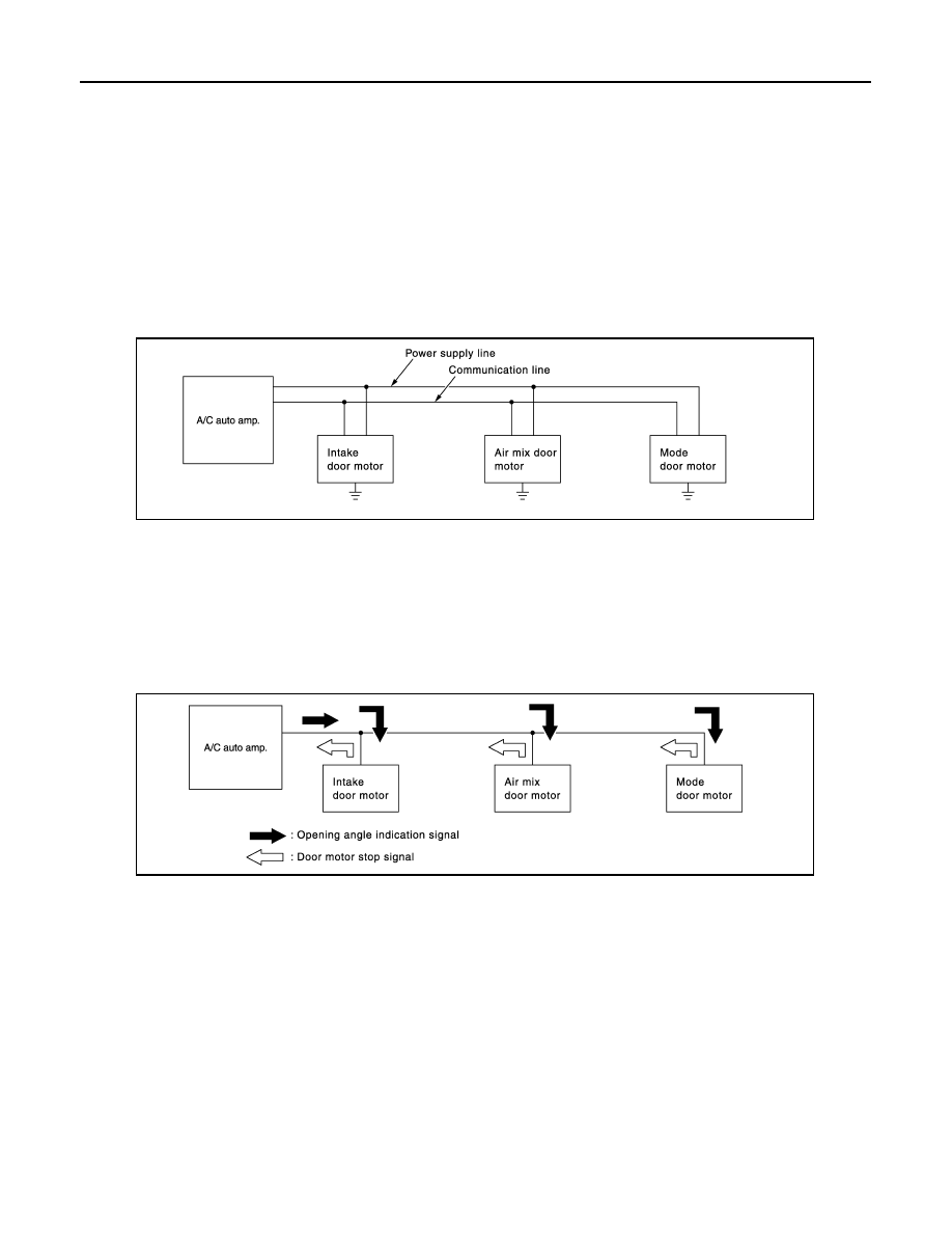
A small network exists between the A/C auto amp., the mode door motor, the air mix door motor and the intake
door motor. The A/C auto amp. and motors are connected by data transmission lines and motor power supply
lines. The LAN network is built through the ground circuits of each door motor.
Addresses, motor opening angle signals, motor stop signals and error checking messages are all transmitted
through the data transmission lines connecting the A/C auto amp. and each door motor.
The following functions are contained in LCUs built into the mode door motor, the air mix door motors and the
intake door motor.
• Address
• Motor opening angle signals
• Data transmission
• Motor stop and drive decision
• Opening angle sensor (PBR function)
• Comparison
• Decision (A/C auto amp. indicated value and motor opening angle comparison)

Operation

The A/C auto amp. receives data from each of the sensors. The A/C auto amp. sends mode door, the air mix
door and the intake door opening angle data to the mode door motor LCU, the air mix door motor LCUs and
the intake door motor LCU.
The mode door motor, the air mix door motors and the intake door motor read their respective signals accord-
ing to the address signal. Opening angle indication signals received from the A/C auto amp. and each of the
motor position sensors is compared by the LCUs in each door motor with the existing decision and opening
angles. Next, HOT/COLD, DEF/VENT, OPEN/SHUT or FRE/REC operation is selected. The new selection
data is returned to the A/C auto amp.

Transmission Data and Transmission Order

A/C auto amp. data is transmitted consecutively to each of the door motors following the form as shown in the
figure below.

START:

• Initial compulsory signal is sent to each of the door motors.

ADDRESS:

• Data sent from the A/C auto amp. is selected according to data-based decisions made by the mode door

motor, the air mix door motors and the intake door motor.

• If the addresses are identical, the opening angle data and error check signals are received by the door motor

LCUs. The LCUs then make the appropriate error decision. If the opening angle data has no error, door con-
trol begins.

• If an error exists, the received data is rejected and the corrected data received. Finally, door control is based

upon the corrected opening angle data.

OPENING ANGLE:

• Data that shows the indicated door opening angle of each door motor.

JMIIA0748GB

JMIIA0749GB

SYSTEM

HAC-19

< SYSTEM DESCRIPTION >

[AUTOMATIC AIR CONDITIONER]

C

D

E

F

G

H

J

K

L

M

A

B

HAC

N

O

P

ERROR CHECK:

• In this procedure, transmitted and received data is checked for errors. Error data is then compiled. The error

check prevents corrupted data from being used by the mode door motor, the air mix door motors and the
intake door motor. Error data can be related to the following symptoms.

- Malfunction of electrical frequency
- Poor electrical connections
- Signal leakage from transmission lines
- Signal level fluctuation

STOP SIGNAL:

• At the end of each transmission, a stop operation, in-operation, or internal malfunction message is delivered

to the A/C auto amp. This completes one data transmission and control cycle.

Temperature Control

INFOID:0000000006043962

• When ignition switch is in the ON position, A/C auto amp. always

automatically controls temperature regardless of air conditioner
operational state.

• A/C auto amp. calculates the target air mix door opening angle

depending on set temperature, in-vehicle temperature, ambient
temperature, and sunload. 

• Air mix door is controlled depending on the comparison of current

air mix door opening angle and target air mix door opening angle.

• Regardless of in-vehicle temperature, ambient temperature, and

sunload, air mix door is fixed at the fully cold position when set
temperature is 18

°

C (60

°

F), and at the fully hot position when set

temperature is 32

°

C (90

°

F).

JMIIA0750GB

JPIIA0633GB

HAC-20

< SYSTEM DESCRIPTION >

[AUTOMATIC AIR CONDITIONER]

OPERATION

OPERATION

Switch Name and Function

INFOID:0000000006024015

CONTROLLER (A/C CONTROL)

SWITCH OPERATION

1.

DEF switch

2.

Fan control switch

3.

OFF switch

4.

MODE switch

5.

REC switch

6.

FRE switch

7.

A/C switch

8.

Temperature control switch

9.

AUTO switch

10. Rear window defogger switch

11.

A/C display

JPIIA1653ZZ

DEF switch

• DEF switch indicator is turned ON 

 OFF by pressing DEF switch each time.

• When DEF switch is operated while air conditioner system is activated, the system becomes the 

following states.

- Compressor: ON 
- Air inlet: Fresh air intake
- Blower fan: Auto control (if blower fan is set to manual mode before pressing DEF switch, it be-

comes manual mode)

- When DEF mode set to OFF, air conditioner system returns previous condition which is set to DEF 

mode.   

• When DEF switch is operated while air conditioner system is inactivation, the system becomes the 

following states.

- Air conditioner system: ON 
- Compressor: ON
- Air inlet: Fresh air intake
- Blower fan: Auto control
• When DEF mode set to OFF, all air conditioner system is OFF.
NOTE:
When DEF mode is set to ON during auto control of air conditioner system, the system becomes man-
ual control. 

Fan control switch

Fan speed is selected within a range between 1st – 7th speed by pressing this switch.
NOTE:
• When air conditioner system is OFF, air conditioner system is set to ON by pressing this switch. 
• When fan control switch is operated during auto control of air conditioner system, the system be-

comes manual mode.

OFF switch

• Air conditioner system is turned OFF by pressing this switch.
• When the air conditioner system becomes OFF, air inlet and outlet are set as follows:
- Air inlet: FRE (except REC is manually selected)
- Air outlet: FOOT 

OPERATION

HAC-21

< SYSTEM DESCRIPTION >

[AUTOMATIC AIR CONDITIONER]

C

D

E

F

G

H

J

K

L

M

A

B

HAC

N

O

P

Mode switch

• Mode position is changed in order of VENT 

 B/L 

 FOOT 

 D/F 

 VENT by operating this 

switch each time.

• When D/F is selected while blower motor is activated, air conditioner system becomes the following 

states.

- Compressor: ON
- Air inlet: Fresh air intake
NOTE:
When MODE switch is operated during auto control of air conditioner system, the system becomes 
manual mode.

REC switch

Air inlet is selected to recirculation (REC) by pressing this switch.
• REC  indicator  ON
• FRE indicator OFF
NOTE:
• Even if the air conditioner system is OFF, air inlet can be selected.
• When mode position is D/F or DEF, recirculation (REC) cannot be selected.
• When REC switch is selected, the compressor is turned ON.
• When REC indicator is ON, pressing the REC switch for approximately 1.5 seconds or more, and 

then the FRE and REC switch indicators blink twice and the system is switched to the automatic 
control.

FRE switch

Air inlet is selected to fresh air intake (FRE) by pressing this switch.
• FRE indicator: ON
• REC indicator: OFF
NOTE:
• Even if the air conditioner system is OFF, air inlet can be selected.
• When mode position is D/F or DEF, air inlet is set to FRE forcibly.
• When FRE indicator is ON, pressing the FRE switch for approximately 1.5 seconds or more, and 

then the FRE and REC switch indicators blink twice and the system is switched to the automatic 
control.

Temperature control 
switch

Setting temperature is selected within a range between 18

°

C (60

°

F) – 32

°

C (90

°

F) by pressing this 

switch.


:  Increase


:  Decrease

NOTE:
Even if air conditioner system is OFF, setting temperature can be selected by pressing these switch.

A/C switch

The compressor control (switch indicator) is turned between ON 

 OFF by pressing this switch each 

time only when blower fan is activated.
NOTE:
• When blower fan is inactivation, compressor control can not be turned ON.
• When mode position is D/F or DEF, A/C switch is turned ON forcibly.

Rear window defogger 
switch

Rear window defogger (switch indicator) is turned between ON 

 OFF by pressing this switch each 

time.
Rear window defogger system details. Refer to 

XX-XX, "*****"

.


Content   ..  369  370  371  372   ..