Nissan March K13. Manual - part 370


  Index      Nissan     Nissan March K13 - Service and Repair Manual)


Search            


Content   ..  368  369  370  371   ..


Nissan March K13. Manual - part 370


HAC-14

< SYSTEM DESCRIPTION >

[AUTOMATIC AIR CONDITIONER]

SYSTEM

• A/C auto amp. changes duty ratio of blower motor drive signal and controls air flow continuously. When air

flow is increased, duty ratio of blower motor drive signal gradually increases to prevent a sudden increase in
air flow.

• In addition to manual control and automatic control, air flow control is compose of starting fan speed control,

low coolant temperature starting control, high in-vehicle temperature starting control, and blower speed con-
trol at door motor operation.

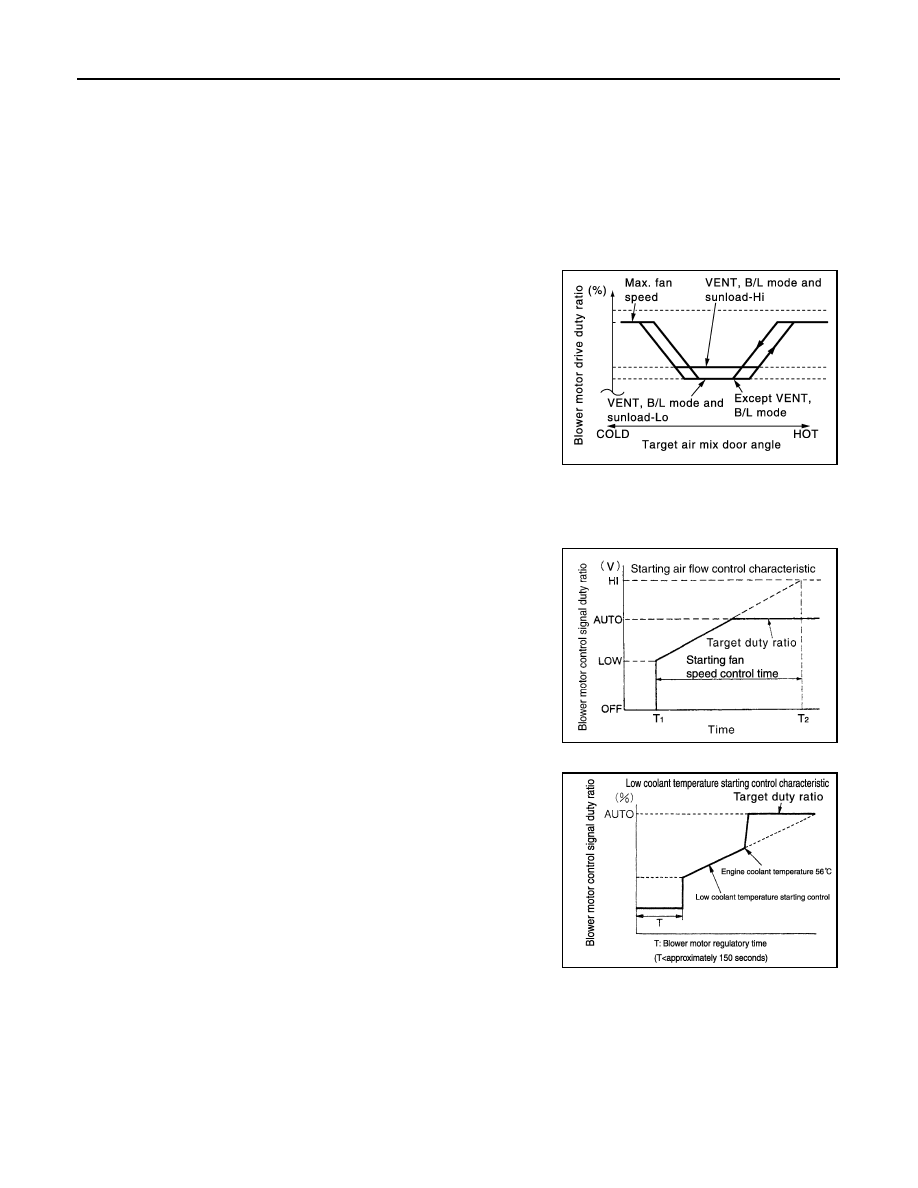
AUTOMATIC AIR FLOW CONTROL

• A/C auto amp. decides target air flow depending on target air mix door opening angle.
• A/C auto amp. changes duty ratio of blower motor drive signal and controls air flow continuously so that air

flow matches to target air flow.

• When air outlet is VENT or B/L, the minimum air flow is changed

depending on sunload.

STARTING FAN SPEED CONTROL

When blower motor is activated, A/C auto amp. gradually increases duty ratio of blower fan drive signal to pre-
vent a sudden increase in discharge air flow. (T

1 –

 T

2

 = approximately 10 seconds)

NOTE:
Do not perform the starting air flow control when the discharge outlet
is set to DEF.

LOW COOLANT TEMPERATURE STARTING CONTROL

If the engine coolant temperature is 56

°

C (133

°

F) or less, to prevent

a cold discharged air flow, A/C auto amp. suspends blower motor
activation for the maximum 150 seconds depending on target air mix
door opening angle. After this, blower fan drive signal is increased
gradually, and blower motor is activated.

FAN SPEED CONTROL AT DOOR MOTOR OPERATION

When mode door motor is activated while air flow is more than the specified value, A/C auto amp. reduces
temporarily fan speed so that mode door moves smoothly.

HIGH IN- TEMPERATURE STARTING CONTROL

When evaporator temperature is high [intake air temperature sensor value is 35

°

C (95

°

F) or more], to prevent

a hot discharged air flow, A/C auto amp. suspends blower motor activation for approximately 3 seconds so
that evaporator is cooled by refrigerant.

JMIIA0712GB

JPIIA1655GB

JSIIA1529GB

SYSTEM

HAC-15

< SYSTEM DESCRIPTION >

[AUTOMATIC AIR CONDITIONER]

C

D

E

F

G

H

J

K

L

M

A

B

HAC

N

O

P

Air Inlet Control

INFOID:0000000006043959

• While air inlet is in automatic control, A/C auto amp. selects air

inlet (fresh air intake, 20% fresh air intake, or recirculation)
depending on set temperature, in-vehicle temperature, and ambi-
ent temperature.

• Air inlet is fixed to 80% FRE, only when the conditions are satisfied

as follows:

- Air inlet is FOOT or D/F
- Ambient temperature is 2

°

C (36

°

F) or less

- Maximum fan speed

Air Outlet Control

INFOID:0000000006043960

• While air outlet is in automatic control, A/C auto amp. selects the

mode door position depending on a target air mix door angle and
outlet air temperature calculated from sunload.

• If ambient temperature is excessively low, D/F is selected to pre-

vent windshield fogging when air outlet is set to FOOT.

Compressor Control

INFOID:0000000006043956

DESCRIPTION

• When the compressor activation condition is satisfied while blower motor is activated, A/C auto amp. trans-

mits A/C ON signal and blower fan ON signal to BCM.

• BCM transmits A/C ON signal and blower fan ON signal to ECM via CAN communication.
• ECM judges that the compressor can be activated depending on each sensors state (refrigerant pressure

sensor signal, throttle opening angle sensor signal, and others). And transmits A/C relay control signal to
IPDM E/R via CAN communication.

• IPDM E/R turns A/C relay ON and activates the compressor depending on request from ECM.

COMPRESSOR PROTECTION CONTROL AT PRESSURE MALFUNCTION

When high-pressure side value that is detected by refrigerant pressure sensor is as per the following state,
ECM requests IPDM E/R to turn A/C relay OFF and stops the compressor.
• 3.12 MPa (31.8 kg/cm

2

, 452 psi) or more (When the engine speed is less than 1,500 rpm)

• 2.74 MPa (27.9 kg/cm

2

, 397 psi) or more (When the engine speed is 1,500 rpm or more)

• 0.14 MPa (1.4 kg/cm

2

, 20 psi) or less

COMPRESSOR OIL CIRCULATION CONTROL

When the engine starts while the engine coolant temperature is 56

°

C (133

°

F) or less, ECM activates the com-

pressor for approximately 6 seconds and circulates the compressor lubricant once.

LOW TEMPERATURE PROTECTION CONTROL

JMIIA0711GB

JMIIA0710GB

HAC-16

< SYSTEM DESCRIPTION >

[AUTOMATIC AIR CONDITIONER]

SYSTEM

When intake sensor detects that evaporator surface temperature is
2

°

C (36

°

F) or less, A/C auto amp. requests ECM to turn the com-

pressor OFF, and stops the compressor.
When the air temperature returns to 3.5

°

C (38

°

F) or more, the com-

pressor is activated.

OPERATING RATE CONTROL

When set temperature is other than fully cold or air outlet is “VENT”, “B/L” or “FOOT” A/C auto amp. controls
the compressor activation depending on ambient temperature.

AIR CONDITIONER CUT CONTROL

When the engine is running in excessively high load condition, ECM requests IPDM E/R to turn A/C relay OFF,
and stops the compressor. Refer to 

XX-XX, "*****"

 for details.

Door Control

INFOID:0000000006043961

SWITCH AND THEIR CONTROL FUNCTION

SJIA0802E

1.

Intake door

2.

Blower motor

3.

Evaporator

4.

Air mix door

5.

Heater core

6.

Foot door

7.

Ventilator and defroster door

Fresh air intake

Recirculation air

Defroster

Center ventilator

Side ventilator

Foot

JMIIA0689ZZ

SYSTEM

HAC-17

< SYSTEM DESCRIPTION >

[AUTOMATIC AIR CONDITIONER]

C

D

E

F

G

H

J

K

L

M

A

B

HAC

N

O

P

*: Inlet status is displayed by indicator during activating automatic control

AIR DISTRIBUTION

AIR CONDITIONER LAN CONTROL SYSTEM

The LAN (Local Area Network) system consists of the A/C auto amp., the mode door motor, the air mix door
motors and the intake door motor.
A configuration of these components is as shown in the figure below.

SYSTEM CONSTRUCTION

Switch position

Door position

V

e

n

ti

la

to

r an

de

fr

ost

e

r do

or

F

o

ot

 do

or

In

ta

ke

 do

or

Ai

r mi

do

or

AUTO switch

AUTO

MODE switch

B

A

A – B

A

B

A – B

DEF switch

A

REC switch*

B

FRE switch*

A

Temperature control 

switch

Full cold

18

°

C (60

°

F)

A

19

°

C – 31

°

C

(61

°

F – 89

°

F)

AUTO

Full hot

32

°

C (90

°

F)

B

OFF switch

OFF

A

A

B

Discharge air flow

Mode position indication

Air outlet/distribution

Center ventilator

Side ventilator

Foot

Defroster

50%

50%

30%

30%

40%

7%

7%

66%

20%

7%

7%

51%

35%

22%

78%

JSIIA1129GB


Content   ..  368  369  370  371   ..