Nissan March K13. Manual - part 330
FRONT DRIVE SHAFT
FAX-19
< REMOVAL AND INSTALLATION >
C
E
F
G
H
I
J
K
L
M
A
B
FAX
N
O
P
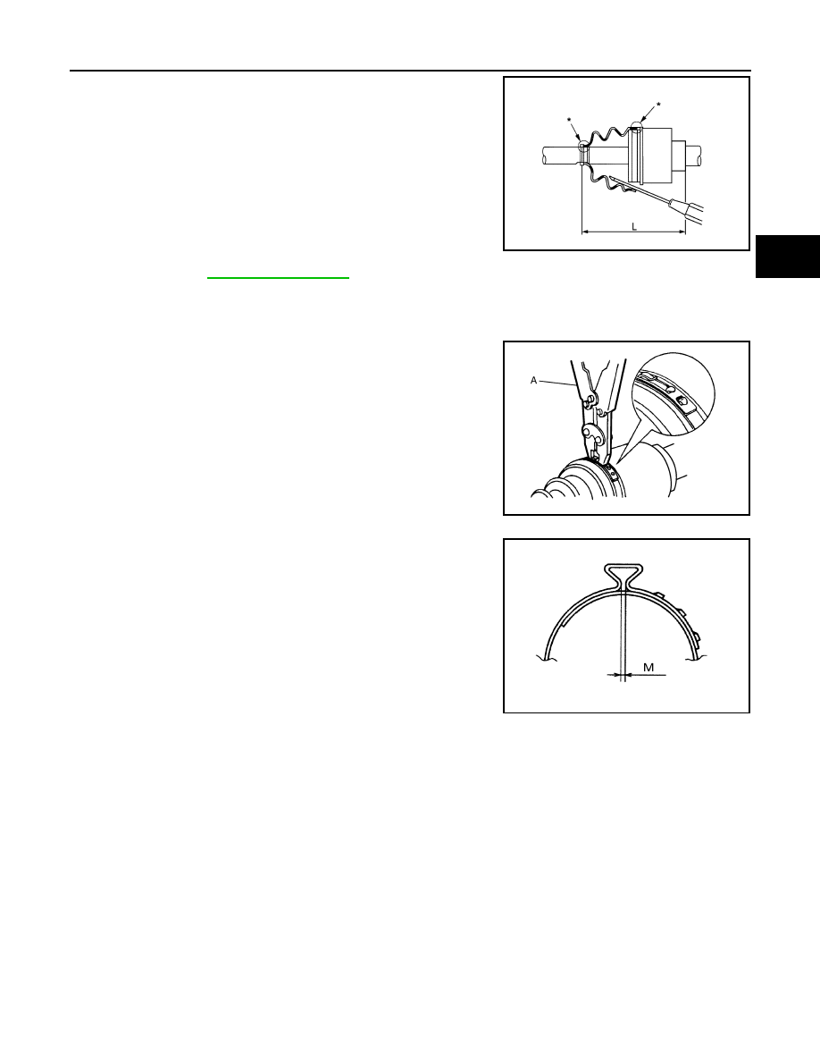
9.
Install the boot securely into grooves (indicated by “*” marks)
shown in the figure.
CAUTION:
If grease adheres to the boot mounting surface (indicated
by “*” mark) on the shaft or joint sub-assembly, boot may
be removed. Remove all grease from the boot mounting
surface.
10. To prevent the deformation of the boot, adjust the boot installa-
tion length (L) to the specified value shown below by inserting
the suitable tool into inside of the boot from the large diameter
side of the boot and discharging the inside air.
CAUTION:
• If the boot installation length exceeds the standard, it may cause breakage of the boot.
• Be careful not to touch the inside of the boot with a tip of tool.
11. Secure the large and small ends of the boot with boot bands
using the boot band crimping tool (SST: KV40107300) (A).
CAUTION:
• Never reuse boot band.
• Secure boot band so that dimension (M) meets the speci-
fication as shown in the figure.
12. Secure joint sub-assembly and shaft, and then check that they
are in the correct position when rotating boot. Reinstall them
using boot bands when boot installation positions become incor-
rect.
CAUTION:
Never reuse boot band.
TRANSAXLE SIDE
TRANSAXLE SIDE : Disassembly and Assembly
INFOID:0000000006044471
DISASSEMBLY
1.
Fix shaft with a vise.
CAUTION:
Protect shaft using aluminum or copper plates when fixing with a vise.
2.
Remove boot bands, and then remove boot from housing.
3.
Put matching marks on housing and shaft, and then pull out housing from shaft.
CAUTION:
Use paint or an equivalent for matching marks. Never scratch the surfaces.
L
: Refer to
.
JPDIF0230ZZ
JPDIF0012ZZ
M
: 1.0 – 4.0 mm (0.039 – 0.157 in)
DSF0047D