Nissan March K13. Manual - part 328


  Index      Nissan     Nissan March K13 - Service and Repair Manual)


Search            


Content   ..  326  327  328  329   ..


Nissan March K13. Manual - part 328


FRONT WHEEL HUB AND KNUCKLE

FAX-11

< REMOVAL AND INSTALLATION >

C

E

F

G

H

I

J

K

L

M

A

B

FAX

N

O

P

3.

Install wheel hub, using the drift (SST) and the drift (SST).

Inspection

INFOID:0000000006044463

INSPECTION AFTER REMOVAL

Check the following items, and replace the part if necessary.
• Check components for deformation, cracks, and other damage.
• Check boots of transverse link and steering outer socket ball joint for breakage, axial end play, and swing

torque. Refer to 

XX-XX, "*****"

 and 

XX-XX, "*****"

.

INSPECTION AFTER DISASSEMBLY

Wheel Hub

• Check wheel hub for cracks (with magnetic exploration or dye testing). Replace if necessary.

Steering Knuckle

• Check steering knuckle for deformation, cracks, and other damage. Replace if any non-standard conditions

are found.

Snap Rings

• Check snap ring for wear or cracks. Replace if necessary.

INSPECTION AFTER ASSEMBLY

1.

Apply a load of 34,300 to 49,000 N (3,500 to 5,000 kg, 7,710 - 11,015 lb). In this condition, rotate in for-
ward and reverse directions 10 times each to insure a good fit.
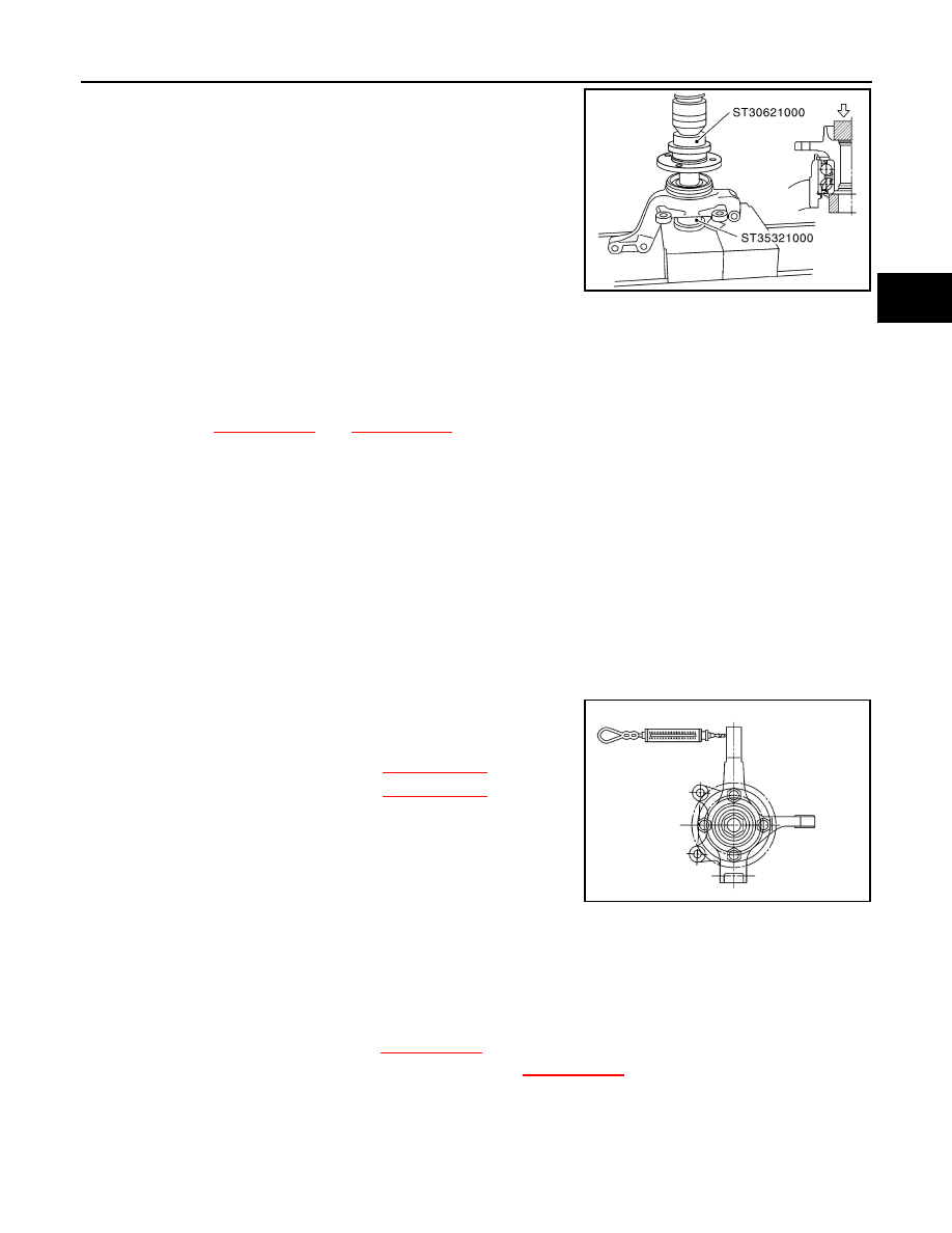
2.

Set a spring balance on strut mounting hole (upper). Measure
rotating torque at an rpm of 8 - 12 rpm.

NOTE:
In case the above loading is not possible
• Assemble drive shaft and tighten wheel hub lock nuts to specified

torque. Then rotate in forward and reverse direction 10 times each
to insure a good fit.

• At a rotating speed of 8 - 12 rpm, place a spring balance on hub bolt to measure torque.

INSPECTION AFTER INSTALLATION

1.

Check the wheel alignment. Refer to 

XX-XX, "*****"

.

2.

Adjust neutral position of steering angle sensor. Refer to 

XX-XX, "*****"

.

MDIA0037E

Rotating torque

: Refer to 

XX-XX, "*****"

.

Spring balance 
measurement

: Refer to 

XX-XX, "*****"

.

Rotating torque

: 2.32 N·m (0.24 kg-m, 21 in-lb) or less

Spring balance measurement

: 15.9 N (1.6 kg, 3.57 lb) or less

SDIA0762J

FAX-12

< REMOVAL AND INSTALLATION >

FRONT DRIVE SHAFT BOOT

FRONT DRIVE SHAFT BOOT

Exploded View

INFOID:0000000006068168

LEFT SIDE

RIGHT SIDE

1.

Joint sub-assembly

2.

Circular clip

3.

Boot band

4.

Boot

5.

Shaft

6.

Spider assembly

7.

Snap ring

8.

Housing

9.

Dust shield

: Wheel side

: Fill NISSAN Genuine grease or equivalent.

Refer to 

GI-4, "Components"

 for symbols not described on the above.

JPDIF0282ZZ

1.

Circular clip

2.

Dust shield

3.

Housing

4.

Snap ring

5.

Spider assembly

6.

Boot band

7.

Boot

8.

Shaft

9.

Damper band

10. Dynamic damper

11.

Circular clip

12. Joint sub-assembly

: Wheel side

JPDIF0269ZZ

FRONT DRIVE SHAFT BOOT

FAX-13

< REMOVAL AND INSTALLATION >

C

E

F

G

H

I

J

K

L

M

A

B

FAX

N

O

P

WHEEL SIDE

WHEEL SIDE : Removal and Installation

INFOID:0000000006044465

REMOVAL

1.

Remove tires. Refer to 

XX-XX, "*****"

.

2.

Remove lock plate from strut assembly. Refer to 

XX-XX, "*****"

.

3.

Remove caliper assembly. Hang caliper assembly not to interfere with work. Refer to 

XX-XX, "*****"

 .

CAUTION:

Never depress brake pedal while brake caliper is removed.

4.

Remove disc rotor.

5.

Remove cotter pin, and then loosen wheel hub lock nut. Refer to 

FAX-9, "Exploded View"

.

6.

Patch wheel hub lock nut with a piece of wood. Hammer the wood to disengage wheel hub from drive
shaft.

CAUTION:

• Never place drive shaft joint at an extreme angle. Also be careful not to overextend slide joint.
• Never allow drive shaft to hang down without support for joint sub-assembly, shaft and the other

parts.

NOTE:
Use suitable puller, if wheel hub and drive shaft cannot be separated even after performing the above pro-
cedure.

7.

Remove wheel hub lock nut.

8.

Remove strut assembly from steering knuckle. Refer to 

XX-XX, "*****"

.

9.

Remove drive shaft from wheel hub.

10. Remove boot bands, and then remove boot from joint subassembly.
11. Screw drive shaft puller (commercial service tool) (A) into joint

sub-assembly screw part to a length of 30 mm (1.18 in) or more.
Support drive shaft with one hand and pull out joint sub-assem-
bly from shaft.

CAUTION:

• Align drive shaft puller and drive shaft and remove them

by pulling firmly and uniformly.

• If joint sub-assembly cannot be pulled out, try after

removing drive shaft from vehicle. Refer to 

FAX-18,

"WHEEL SIDE : Disassembly and Assembly"

.

12. Remove circular clip from shaft.

13. Remove boot from shaft.

INSTALLATION

1.

Clean the old grease on joint sub-assembly with paper waste.

2.

Fill serration slot joint sub-assembly with NISSAN genuine grease or equivalent until the serration slot and
ball groove become full to the brim.

CAUTION:

After applying grease, use a paper waste to wipe off old grease that has oozed out.

3.

Install boot and boot bands to shaft.

CAUTION:

• Wrap serration on shaft with tape to protect the boot from damage.
• Never reuse boot and boot band.

4.

Remove the tape wrapped around the serration on shaft.

5.

Position the circular clip on groove at the shaft edge.

CAUTION:

: Fill NISSAN Genuine grease or equivalent.

Refer to 

GI-4, "Components"

 for symbols not described on the above.

JPDIF0258ZZ

FAX-14

< REMOVAL AND INSTALLATION >

FRONT DRIVE SHAFT BOOT

Never reuse circular clip.
NOTE:
Drive joint inserter is recommended when installing circular clip.

6.

Align both center axles of the shaft edge and joint sub-assembly. Then assemble shaft with joint sub-
assembly holding circular clip.

7.

Install joint sub-assembly (1) to shaft using plastic hammer.

CAUTION:

Confirm that joint sub-assembly is correctly engaged while
rotating drive shaft.

8.

Apply the specified amount of grease into the boot inside from
large diameter side of boot.

9.

Install the boot securely into grooves (indicated by “*” marks)
shown in the figure.

CAUTION:

If grease adheres to the boot mounting surface (indicated
by “*” mark) on the shaft or joint sub-assembly, boot may
be removed. Remove all grease from the boot mounting
surface.

10. To prevent the deformation of the boot, adjust the boot installa-

tion length (L) to the specified value shown below by inserting
the suitable tool into inside of the boot from the large diameter
side of the boot and discharging the inside air.

CAUTION:

• If the boot installation length exceeds the standard, it may cause breakage of the boot.
• Be careful not to touch the inside of the boot with a tip of tool.

11. Secure the large and small ends of the boot with boot bands

using the boot band crimping tool (SST: KV40107300) (A).

CAUTION:

• Never reuse boot band.

• Secure boot band so that dimension (M) meets the speci-

fication as shown in the figure.

12. Secure joint sub-assembly and shaft, and then check that they

are in the correct position when rotating boot. Reinstall them
using boot bands when boot installation positions become incor-
rect.

CAUTION:

Never reuse boot band.

13. Clean the matching surface of wheel hub lock nut and wheel

hub.

Grease amount

: Refer to 

FAX-23, "Drive Shaft"

.

JPDIF0011ZZ

L

:  Refer  to 

FAX-23, "Drive Shaft"

.

JPDIF0230ZZ

JPDIF0012ZZ

M

: 1.0 – 4.0 mm (0.039 – 0.157 in)

DSF0047D


Content   ..  326  327  328  329   ..