Nissan March K13. Manual - part 185


  Index      Nissan     Nissan March K13 - Service and Repair Manual)


Search            


Content   ..  183  184  185  186   ..


Nissan March K13. Manual - part 185


P0340 CMP SENSOR (PHASE)

EC-201

< DTC/CIRCUIT DIAGNOSIS >

[HR12DE (TYPE 1)]

C

D

E

F

G

H

I

J

K

L

M

A

EC

N

P

O

Is the inspection result normal?

YES

>> GO TO 3.

NO

>> Repair open circuit or short to ground or short to power in harness or connectors.

3.

CHECK CMP SENSOR (PHASE) GROUND CIRCUIT FOR OPEN AND SHORT

1.

Turn ignition switch OFF.

2.

Disconnect ECM harness connectors.

3.

Check the continuity between CMP sensor (PHASE) harness connector and ECM harness connector.

4.

Also check harness for short to ground and short to power.

Is the inspection result normal?

YES

>> GO TO 4.

NO

>> Repair open circuit or short to ground or short to power in harness or connectors.

4.

CHECK CMP SENSOR (PHASE) INPUT SIGNAL CIRCUIT FOR OPEN AND SHORT

1.

Check the continuity between CMP sensor (PHASE) harness connector and ECM harness connector.

2.

Also check harness for short to ground and short to power.

Is the inspection result normal?

YES

>> GO TO 5.

NO

>> Repair open circuit or short to ground or short to power in harness or connectors.

5.

CHECK CAMSHAFT POSITION SENSOR (PHASE)

Check camshaft position sensor (phase). Refer to 

EC-202, "Component Inspection"

.

Is the inspection result normal?

YES

>> GO TO 6.

NO

>> Replace camshaft position sensor (PHASE). Refer to 

EM-53, "Exploded View"

.

6.

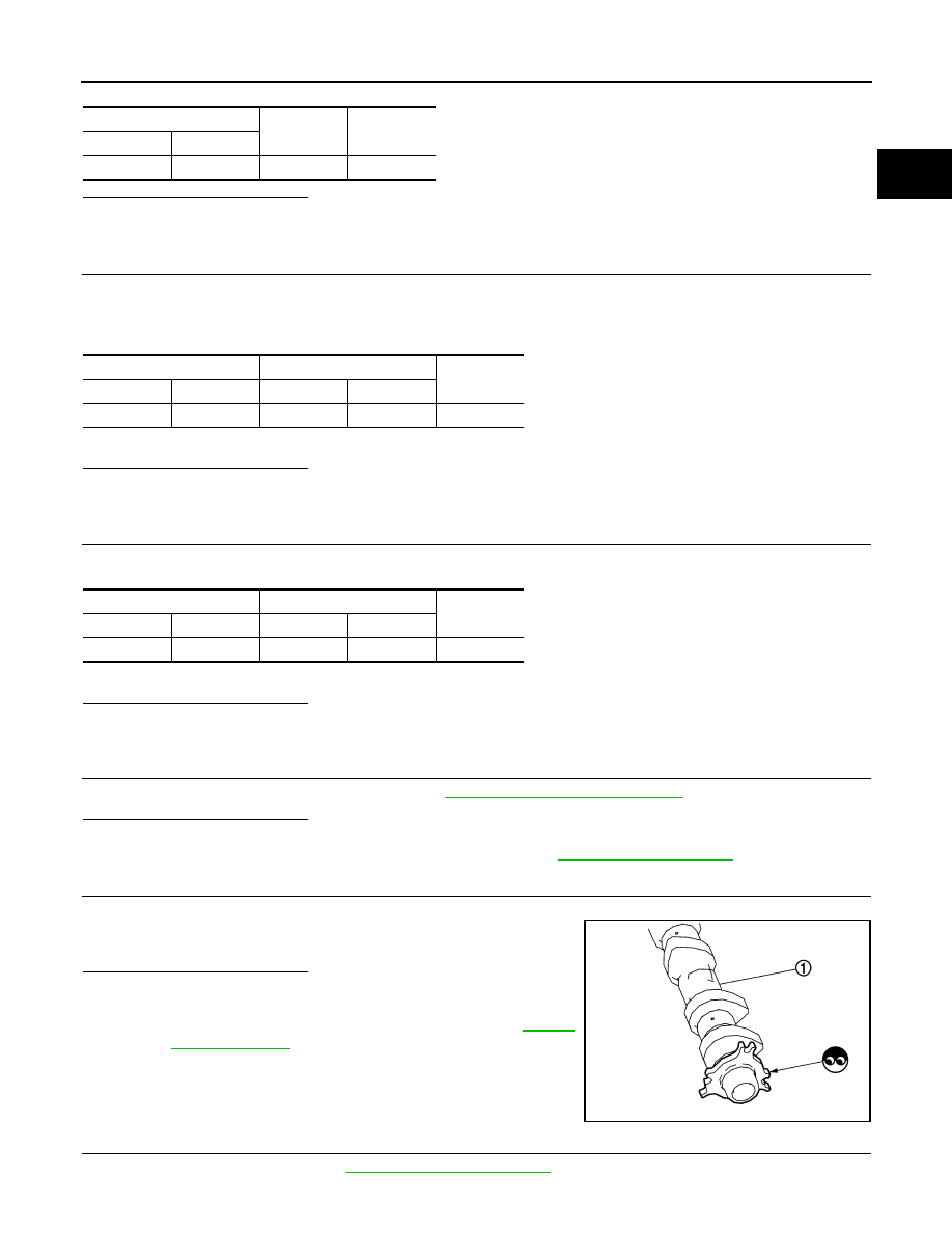
CHECK CAMSHAFT (INT)

Check the following.
• Accumulation of debris to the signal plate of camshaft (1) rear end
• Chipping signal plate of camshaft rear end

Is the inspection result normal?

YES

>> GO TO 7.

NO

>> Remove debris and clean the signal plate of camshaft

rear end or replace camshaft. Refer to 

EM-53,

"Exploded View"

.

7.

CHECK INTERMITTENT INCIDENT

Check intermittent incident. Refer to 

GI-33, "Intermittent Incident"

.

CMP sensor (PHASE)

Ground

Voltage

Connector

Terminal

F26

1

Ground

Approx. 5 V

CMP sensor (PHASE)

ECM

Continuity

Connector

Terminal

Connector

Terminal

F26

2

F16

63

Existed

CMP sensor (PHASE)

ECM

Continuity

Connector

Terminal

Connector

Terminal

F26

3

F16

65

Existed

JSBIA0340ZZ

EC-202

< DTC/CIRCUIT DIAGNOSIS >

[HR12DE (TYPE 1)]

P0340 CMP SENSOR (PHASE)

>> Repair or replace malfunctioning part.

Component Inspection

INFOID:0000000005989297

1.

CHECK CAMSHAFT POSITION SENSOR (PHASE)-I

1.

Turn ignition switch OFF.

2.

Loosen the fixing bolt of the sensor.

3.

Disconnect camshaft position sensor (PHASE) harness connector.

4.

Remove the sensor.

5.

Visually check the sensor for chipping.

Is the inspection result normal?

YES

>> GO TO 2.

NO

>> Replace camshaft position sensor (PHASE). Refer to

EM-53, "Exploded View"

.

2.

CHECK CAMSHAFT POSITION SENSOR (PHASE)-II

Check resistance camshaft position sensor (PHASE) terminals as follows.

Is the inspection result normal?

YES

>> INSPECTION END

NO

>> Replace camshaft position sensor (PHASE). Refer to 

EM-53, "Exploded View"

.

PBIA9210J

Terminals (Polarity)

Resistance [at 25

°

C (77

°

F)]

1 (+) - 2 (

)

Except 0 or 


1 (+) - 3 (

)

2 (+) - 3 (

)

P0400 EGR FUNCTION

EC-203

< DTC/CIRCUIT DIAGNOSIS >

[HR12DE (TYPE 1)]

C

D

E

F

G

H

I

J

K

L

M

A

EC

N

P

O

P0400 EGR FUNCTION

DTC Logic

INFOID:0000000006015155

DTC DETECTION LOGIC

DTC CONFIRMATION PROCEDURE

1.

PRECONDITIONING

If DTC Confirmation Procedure has been previously conducted, always turn ignition switch OFF and wait atle-
ast 10 seconds before conducting the next test.
TESTING CONDITION:
Before performing the following procedure, confirm that battery voltage is more than 10 V at idle.

>> GO TO 2.

2.

PERFORM DTC CONFIRMATION PROCEDURE

With CONSULT-III

1.

Turn ignition switch ON.

2.

Check “COOLAN TEMP/S” in “DATA MONITOR” mode with CONSULT-III.

3.

Confirm “COOLAN TEMP/S” value is within the range listed below.

If the value is out of range, park the vehicle in a cool place and allow the engine temperature to stabilize.

CAUTION:

Do not attempt to lower the engine coolant temperature with a fan or means other than ambient air.
Doing so may produce an inaccurate diagnostic result.

4.

Start engine and let it idle monitoring “COOLAN TEMP/S” value. When the “COOLAN TEMP/S” value
reaches 70

°

C (158

°

F), immediately go to the next step.

5.

Drive the vehicle for at least 150 consecutive seconds under the following conditions.

CAUTION:

Always drive vehicle at a safe speed.

6.

Stop the engine and let it idle for at least 20 seconds.

7.

Check 1st trip DTC.

With GST

Follow the procedure “With CONSULT-III” above.
Is 1st trip DTC detected?

YES

>> Go to 

EC-204, "Diagnosis Procedure"

.

NO

>> INSPECTION END

DTC No.

Trouble diagnosis name

DTC detecting condition

Possible cause

P0400

EGR function (Close)

No EGR flow is detected under the condi-
tion that calls for EGR.

• Harness or connectors

(The EGR volume control valve circuit 
isopen or shorted.)

• EGR volume control valve stuck closed
• Dead (Weak) battery
• EGR passage clogged
• EGR temperature sensor
• EGR temperature circuit
• Exhaust gas leaks

COOLAN TEMP/S

: Less than 40

°

C (104

°

F)

ENG SPEED

1,000 - 3,200 rpm

VHCL SPEED SE

More than 10 km/h (6 MPH)

B/FUEL SCHDL

4.0 - 12.0 msec

Shift lever

Suitable position

EC-204

< DTC/CIRCUIT DIAGNOSIS >

[HR12DE (TYPE 1)]

P0400 EGR FUNCTION

Diagnosis Procedure

INFOID:0000000006015157

1.

CHECK EXHAUST GAS LEAK

1.

Start the engine and run it at idle.

2.

Check exhaust pipes and muffler for leaks.

Is the inspection result normal?

YES

>> GO TO 2.

NO

>> Repair or replace exhaust system. Refer to 

EX-5, "Exploded View"

.

2.

CHECK EGR VOLUME CONTROL VALVE POWER SUPPLY CIRCUIT

1.

Turn ignition switch OFF.

2.

Disconnect EGR volume control valve harness connector.

3.

Turn ignition switch ON.

4.

Check voltage between EGR volume control valve connector and ground.

Is the inspection result normal?

YES

>> GO TO 4.

NO

>> GO TO 3.

3.

DETECT MALFUNCTIONING PART

Check harness for open or short between EGR volume control valve and IPDM E/R.

>> Repair or replace harness or connectors.

4.

CHECK EGR VOLUME CONTROL VALVE OUTPUT SIGNAL CIRCUIT FOR OPEN AND SHORT

1.

Turn ignition switch OFF.

2.

Disconnect ECM harness connector.

3.

Check the continuity between ECM harness connector and EGR volume control valve harness connector.

4.

Also check harness for short to ground and short to power.

Is the inspection result normal?

YES

>> GO TO 5.

NO

>> Repair open circuit or short to power in harness or connectors.

PBIB1216E

EGR volume control valve

Ground

Voltage

Connector

Terminal

F88

2

Ground

Battery voltage

5

EGR volume control valve

ECM

Continuity

Connector

Terminal

Connector

Terminal

F88

1

F7

12

Existed

3

16

4

20

6

24


Content   ..  183  184  185  186   ..