Almera Tino V10 (2003 year). Manual - part 224


  Index      Manuals     Almera Tino V10 (2003 year) - Service and Repair Manual


Search            copyright infringement  


Content      ..     222      223      224      225     ..


Almera Tino V10 (2003 year). Manual - part 224


MT-38

[RS6F51R]

INPUT SHAFT AND GEARS

9.

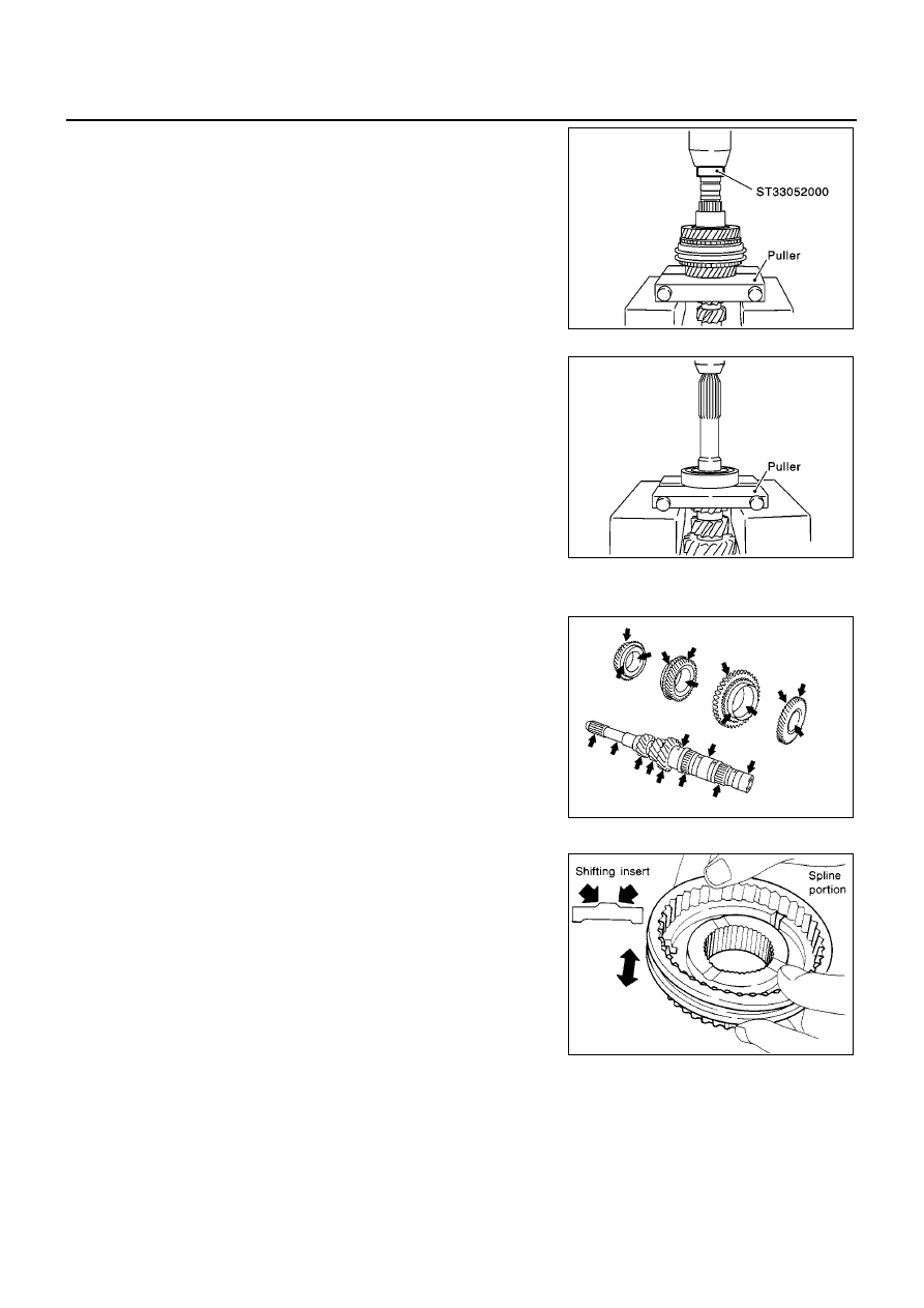
Remove 5th bushing, thrust washer, 4th input gear, 4th needle
bearing, 4th bushing, 4th baulk ring, 3rd-4th synchronizer hub
assembly, 3rd baulk ring and 3rd input gear simultaneously.

10. Remove 3rd needle bearing.

11. Remove input shaft front bearing.

INSPECTION AFTER DISASSEMBLY
Input Shaft and Gear

Check items below. If necessary, replace them with new ones.

Damage, peeling, dent, uneven wear, bending, etc. of shaft

Excessive wear, damage, peeling, etc. of gears

Synchronizer

Check items below. If necessary, replace them with new ones.

Damage and excessive wear of contact surfaces of coupling
sleeve, synchronizer hub, and shifting insert

Coupling sleeve and synchronizer hub must move smoothly.

SCIA0919E

SCIA0920E

SCIA1074J

SMT387A

INPUT SHAFT AND GEARS

MT-39

[RS6F51R]

D

E

F

G

H

I

J

K

L

M

A

B

MT

If any crack, damage, or excessive wear is found on cam face of
baulk ring or working face of insert, replace it.

Baulk ring clearance

Press baulk ring against cone, and measure clearance between
baulk ring and cone. If measurement is below limit, replace it
with a new one.

Bearing

Check items below. If necessary, replace them with new ones.

Damage and rough rotation of bearing

ASSEMBLY

1.

Install 3rd needle bearing.

2.

Install 3rd input gear and 3rd baulk ring.

3.

Install spread spring, shifting insert and 3rd-4th synchronizer
hub onto 3rd-4th coupling sleeve.

CAUTION:

Be careful with orientation of synchronizer hub.

Do not reuse 3rd-4th synchronizer hub.

SMT867D

Clearance

Standard

3rd and 4th

: 0.9 - 1.45 mm (0.0354 - 0.0571 in)

5th and 6th

: 0.95 - 1.4 mm (0.0374 - 0.0551 in)

Limit value

: 0.7 mm (0.0276 in)

SMT140

MTF0041D

SCIA0921E

MT-40

[RS6F51R]

INPUT SHAFT AND GEARS

Be careful with orientation of coupling sleeve.

Be sure not to hook center projection of 2 spread springs
on same shifting insert.

4.

Install 3rd-4th synchronizer hub assembly.

CAUTION:

Align grooves of shifting insert and 3rd baulk ring.

5.

Install 4th bushing.

6.

Install 4th baulk ring.

7.

Install 4th input gear and 4th needle bearing.

SCIA0993E

MCIA0145E

SCIA0922E

SCIA0923E

INPUT SHAFT AND GEARS

MT-41

[RS6F51R]

D

E

F

G

H

I

J

K

L

M

A

B

MT

8.

Select thrust washer so that dimension “C2” satisfies standard
below. Then install it onto input shaft.

Thrust Washer

CAUTION:

Only one thrust wahser can be selected.

9.

Install 5th bushing.

10. Install 5th needle bearing and 5th input gear.

11. Install 5th baulk ring.

12. Install 5th-6th synchronizer hub, spread spring and shifting

insert onto 5th-6th coupling sleeve.

CAUTION:

Be careful with orientation of synchronizer hub.

Do not reuse 5th-6th synchronizer hub.

Standard for dimension C2

: 154.7 - 154.8 mm (6.091 -
6.094 in)

SCIA0925E

Thickness

Part number

Thickness

Part number

3.84 mm (0.1512 in)
3.90 mm (0.1535 in)
3.96 mm (0.1559 in)

32347 8H500
32347 8H501
32347 8H502

4.02 mm (0.1583 in)
4.08 mm (0.1606 in)
4.14 mm (0.1630 in)

32347 8H503
32347 8H504
32347 8H505

SCIA0926E

SCIA0921E

MT-42

[RS6F51R]

INPUT SHAFT AND GEARS

Be sure not to hook center projection of 2 spread springs
on same shifting insert.

13. Install 5th-6th synchronizer hub assembly.

CAUTION:

Align grooves of 5th-6th shifting insert and 5th-6th baulk
ring.

14. Install 6th needle bearing, 6th input gear onto 6th bushing, and

then install them onto input shaft.

15. Install snap ring onto input shaft, and check that end play (gap

between snap ring and groove) of 6th bushing satisfies stan-
dard.

If measurement is outside the standard range, select snap
ring.

SMT136E

SCIA0928E

SCIA0969E

End play standard value

: 0 - 0.1 mm (0 - 0.004 in)

SCIA0970E

INPUT SHAFT AND GEARS

MT-43

[RS6F51R]

D

E

F

G

H

I

J

K

L

M

A

B

MT

Snap Rings

16. Install input shaft rear bearing.

CAUTION:

Install input shaft rear bearing with its brown surface facing
the 6th input gear side.

17. Install input shaft front bearing.

18. Install oil channel onto input shaft.

19. Check end play of 3rd, 4th, 5th and 6th input gears.

Thickness

Part number

Thickness

Part number

1.76 mm (0.0693 in)
1.81 mm (0.0713 in)
1.86 mm (0.0732 in)
1.91 mm (0.0752 in)
1.96 mm (0.0772 in)

32204 8H511

32204 8H512
32204 8H513
32204 8H514
32204 8H515

2.01 mm (0.0791 in)
2.06 mm (0.0811 in)
2.11 mm (0.0831 in)
2.16 mm (0.0850 in)
2.21 mm (0.0870 in)

32204 8H516
32204 8H517
32204 8H518
32204 8H519
32204 8H520

SCIA0971E

SCIA0972E

End play standard value

3rd gear

: 0.18 - 0.31 mm (0.0071 - 0.0122 in)

4th gear

: 0.20 - 0.30 mm (0.0079 - 0.0118 in)

5th gear

: 0.06 - 0.16 mm (0.0024 - 0.0063 in)

6th gear

: 0.06 - 0.16 mm (0.0024 - 0.0063 in)

SCIA0966E

MT-44

[RS6F51R]

MAINSHAFT AND GEARS

MAINSHAFT AND GEARS

PFP:32241

Assembly and Disassembly

ECS0095Y

DISASSEMBLY

1.

Before disassembling, measure end play of 1st and 2nd main
gears.

2.

Remove the snap ring.

3.

Remove C-ring holder, and then mainshaft C-ring.

4.

Remove mainshaft rear bearing, adjust shim and 6th main gear.

5.

Remove 5th-6th mainshaft spacer.

6.

Remove 4th main gear and 5th main gear simultaneously.

7.

Remove adjusting shim.

8.

Remove 3rd & 4th mainshaft spacer.

End play standard value

1st gear

: 0.20 - 0.30 mm (0.0079 - 0.0118 in)

2nd gear

: 0.06 - 0.16 mm (0.0024 - 0.0063 in)

SCIA0973E

SCIA0974E

SCIA0976E

SCIA0937E

MAINSHAFT AND GEARS

MT-45

[RS6F51R]

D

E

F

G

H

I

J

K

L

M

A

B

MT

9.

Remove 3rd main gear, 2nd main gear, 2nd gear needle bear-
ing, 2nd bushing, 1st-2nd synchronizer assembly, 1st main gear,
reverse main gear, 1st gear needle bearing, and 1st bushing
simultaneously.

INSPECTION AFTER DISASSEMBLY
Mainshaft and Gears

Check items below. If necessary, replace them with new ones.

Damage, peeling, dent, uneven wear, bending, and other non-
standard conditions of the shaft.

Excessive wear, damage, peeling, and other non-standard con-
ditions of the gears.

Synchronizer

Check items below. If necessary, replace them with new ones.

Damage and unusual wear on contact surfaces of coupling
sleeve, synchronizer hub, and shifting insert.

Coupling sleeve and synchronizer hub must move smoothly.

If any crack, damage, or excessive wear is found on cam face of
baulk ring or working face of insert, replace it.

SCIA0938E

SCIA1076J

SMT387A

SMT867D

MT-46

[RS6F51R]

MAINSHAFT AND GEARS

Baulk ring clearance

Double cone synchronizer (1st and 2nd)
Check clearance of outer baulk ring, synchronizer cone, and
inner baulk ring of 1st and 2nd double cone synchronizers, fol-
lowing procedure below.

CAUTION:

Outer baulk ring, synchronizer cone, and inner baulk ring
as a set control clearance A and B. If measurement exceeds
service limit value, replace all of them as a set.

1.

Using a dial gauge, measure clearance A at 2 or more points
diagonally opposite, and calculate mean value.

2.

Using a feeler gauge, measure clearance B at 2 or more points
diagonally opposite, and calculate mean value.

Bearing

Check items below. If necessary, replace them with new ones.

Damage and rough rotation of bearing

SCIA0950E

Clearance A

Standard

: 0.6 - 0.8 mm (0.024 - 0.031 in)

Limit value

: 0.2 mm (0.008 in) or less

SCIA0951E

Clearance B

Standard

: 0.6 - 1.1 mm (0.024 - 0.043 in)

Limit value

: 0.2 mm (0.008 in) or less

SMT139E

MTF0041D

MAINSHAFT AND GEARS

MT-47

[RS6F51R]

D

E

F

G

H

I

J

K

L

M

A

B

MT

ASSEMBLY

1.

Install reverse main gear.

CAUTION:

Be careful with orientation of reverse main gear.

2.

Install 1st bushing.

3.

Install needle bearing, and then 1st main gear.

4.

Install spread spring, shifting insert and 1st-2nd synchronizer
hub onto 1st-2nd coupling sleeve.

CAUTION:

Be careful with orientation of synchronizer hub.

Do not reuse 1st-2nd synchronizer hub.

MCIA0034E

SCIA0992E

SCIA0940E

SCIA0921E

MT-48

[RS6F51R]

MAINSHAFT AND GEARS

Be careful with orientation of coupling sleeve.

Be sure not to hook center projection of 2 spread springs
on same shifting insert.

5.

Install 1st gear synchronizer assembly onto mainshaft, and syn-
chronizer hub assembly onto mainshaft.

CAUTION:

Outer baulk ring, synchronizer cone, and inner baulk ring
on 2nd gear-side must have been removed.

Be careful with orientation of coupling sleeve.

6.

Install 2nd bushing.

7.

Install outer baulk ring, synchronizer cone, and inner baulk ring
on 2nd gear-side.

8.

Install 2nd needle bearing and 2nd gear.

SCIA0989E

MCIA0145E

SCIA0941E

SCIA0942E

MAINSHAFT AND GEARS

MT-49

[RS6F51R]

D

E

F

G

H

I

J

K

L

M

A

B

MT

9.

Install 3rd main gear.

CAUTION:

Be careful with orientation of 3rd main gear.

10. Install 3rd-4th mainshaft spacer.

11. Select suitable adjusting shim so that dimension “C1” satisfies

standard value below, and install it onto mainshaft.

Adjusting Shim

CAUTION:

Only one adjusting shim can be selected.

12. Install 4th main gear.

CAUTION:

Be careful with orientation of 4th main gear.

SCIA0943E

Standard for dimension C1

: 173.85 - 173.95 mm
(6.844 - 6.848 in)

SCIA0944E

Thickness

Part number

Thickness

Part number

0.52 mm (0.0205 in)
0.60 mm (0.0236 in)
0.68 mm (0.0268 in)
0.76 mm (0.0299 in)

32238 8H500
32238 8H501
32238 8H502
32238 8H503

0.84 mm (0.0331 in)
0.92 mm (0.0362 in)
1.00 mm (0.0394 in)
1.08 mm (0.0425 in)

32238 8H504
32238 8H505
32238 8H506
32238 8H507

SCIA0945E

MT-50

[RS6F51R]

MAINSHAFT AND GEARS

13. Install 5th main gear.

CAUTION:

Be careful with orientation of 5th main gear.

14. Install 5th-6th mainshaft spacer.

15. Install 6th main gear.

16. Select 6th main adjusting shim and then install it onto mainshaft.

Calculate thickness “S” of 6th main adjusting shim by proce-
dure below so that end play dimension between 6th main
gear and mainshaft rear bearing becomes the dimension
shown below.

Adjusting Shim

CAUTION:

Only one adjusting shim can be selected.

a.

Using height gauge, measure dimension “S

1

” and “S

2

”.

SCIA0946E

SCIA0977E

End play

: 0 - 0.1 mm (0 - 0.004 in)

Dimension “S” = (S

1

S

2

) + End play

S

: Thickness of adjusting shim

S

1

: Dimension from mainshaft standard face to
mainshaft rear bearing press-fit end face

S

2

: Dimension from mainshaft standard face to
6th main gear end face

SCIA0995E

Thickness

Part number

Thickness

Part number

0.88 mm (0.0346 in)
0.96 mm (0.0378 in)
1.04 mm (0.0409 in)
1.12 mm (0.0441 in)

32237 8H560
32237 8H561
32237 8H562
32237 8H563

1.20 mm (0.0472 in)
1.28 mm (0.0504 in)
1.36 mm (0.0535 in)

32237 8H564
32237 8H565
32237 8H566

MAINSHAFT AND GEARS

MT-51

[RS6F51R]

D

E

F

G

H

I

J

K

L

M

A

B

MT

b.

Install selected 6th main adjusting shim to mainshaft.

17. Install mainshaft rear bearing.

18. Install C-ring onto mainshaft, and check that end play of main-

shaft rear bearing satisfies standard value.

If measurement is outside the standard range, reselect C-ring.

C-ring

19. Fit C-ring holder, and install snap ring.

SCIA0978E

End play standard value

: 0 - 0.06 mm (0 - 0.0024 in)

SCIA0979E

Thickness

Part number

Thickness

Part number

2.535 mm (0.0998 in)
2.565 mm (0.1010 in)
2.595 mm (0.1022 in)
2.625 mm (0.1033 in)
2.655 mm (0.1045 in)
2.685 mm (0.1057 in)
2.715 mm (0.1069 in)
2.745 mm (0.1081 in)
2.775 mm (0.1093 in)

2.805 mm (0.1104 in)

32348 8H800
32348 8H801
32348 8H802
32348 8H803
32348 8H804
32348 8H805
32348 8H806
32348 8H807
32348 8H808
32348 8H809

2.835 mm (0.1116 in)
2.865 mm (0.1128 in)
2.895 mm (0.1140 in)
2.925 mm (0.1152 in)
2.955 mm (0.1163 in)
2.985 mm (0.1175 in)
3.015 mm (0.1187 in)
3.045 mm (0.1199 in)
3.075 mm (0.1211 in)

32348 8H810

32348 8H811

32348 8H812
32348 8H813
32348 8H814
32348 8H815
32348 8H816
32348 8H817
32348 8H818

SCIA0974E

MT-52

[RS6F51R]

MAINSHAFT AND GEARS

20. Check end play of 1st and 2nd main gears.

End play standard value

1st gear

: 0.20 - 0.30 mm (0.0079 - 0.0118 in)

2nd gear

: 0.06 - 0.16 mm (0.0024 - 0.0063 in)

SCIA0973E

REVERSE IDLER SHAFT AND GEARS

MT-53

[RS6F51R]

D

E

F

G

H

I

J

K

L

M

A

B

MT

REVERSE IDLER SHAFT AND GEARS

PFP:32281

Assembly and Disassembly

ECS0095Z

DISASSEMBLY

1.

Remove reverse idler gear adjusting shim.

2.

Remove reverse idler gear (rear), reverse coupling sleeve and insert spring simultaneously.

3.

Remove reverse idler gear needle bearing.

4.

Remove thrust needle bearing.

5.

Remove reverse baulk ring.

6.

Remove reverse idler gear (front).

7.

Remove reverse idler gear needle bearing.

8.

Remove thrust needle bearing.

9.

Pull off locking pin from reverse idler shaft.

INSPECTION AFTER DISASSEMBLY
Reverse Idler Shaft and Gears

Check items below. If necessary, replace them with new ones.

Damage, peeling, dent, uneven wear, bending, and other non-
standard conditions of the shaft.

Excessive wear, damage, peeling, and other non-standard con-
ditions of the gears.

Synchronizer

Check items below. If necessary, replace them with new ones.

Damage and unusual wear on contact surfaces of coupling
sleeve, synchronizer hub, and insert spring.

Coupling sleeve and synchronizer hub must move smoothly.

If any crack, damage, or excessive wear is found on cam face of
baulk ring or working face of insert, replace it.

SCIA0953J

SMT637A

SMT867D


Content      ..     222      223      224      225     ..