Almera Tino V10 (2003 year). Manual - part 223


  Index      Manuals     Almera Tino V10 (2003 year) - Service and Repair Manual


Search            copyright infringement  


Content      ..     221      222      223      224     ..


Almera Tino V10 (2003 year). Manual - part 223


MT-22

[RS6F51R]

TRANSAXLE ASSEMBLY

4.

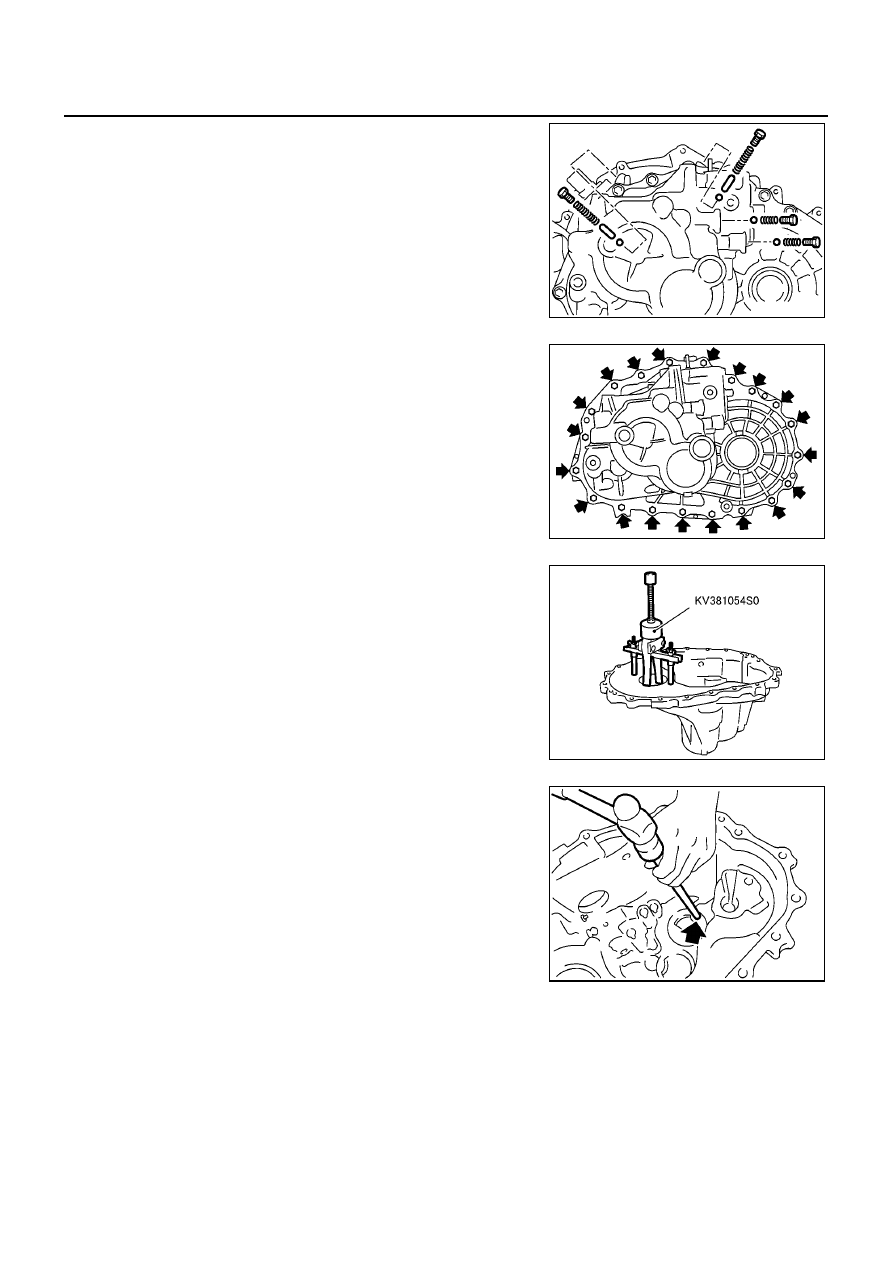
Remove check plugs (4 pieces), check springs (4 pieces), check
balls (4 pieces) and shift check sleeve (2 pieces).

5.

Remove transaxle case fixing bolts.

6.

Remove bore plug.

CAUTION:

Be careful not to damage transaxle case.

7.

While spreading the snap ring of mainshaft rear bearing located
at bore plug hole, remove transaxle case.

8.

Remove oil gutter, baffle plate.

9.

Remove snap ring, mainshaft rear bearing adjusting shim and
input shaft rear bearing adjusting shim from transaxle case.

10. Remove differential side bearing outer race (transaxle case

side) and then adjusting shim.

11. Remove welch plug.

SCIA0959E

SCIA0983E

SCIA0897E

SCIA0402E

TRANSAXLE ASSEMBLY

MT-23

[RS6F51R]

D

E

F

G

H

I

J

K

L

M

A

B

MT

12. Remove differential oil seal (transaxle case side).

13. Remove magnet from clutch housing.

14. With shift lever in 5th position, remove bracket bolts from

reverse lever assembly. Lift reverse lever assembly to remove.

CAUTION:

Be careful not to lose shifter cap.

15. Pull out reverse fork rod then remove reverse shift fork.

16. Remove retaining pin of reverse bracket using pin punch.

17. Pull out reverse bracket and reverse bracket fork rod.

18. Remove check ball (2 pieces) and inter lock pin.

19. Shift 3rd & 4th fork rod to 3rd position. Remove retaining pin of

5th & 6th shift fork using pin punch.

SCIA0397E

SCIA0960E

SCIA0961E

SCIA0962E

MT-24

[RS6F51R]

TRANSAXLE ASSEMBLY

20. Remove stopper rings for 5th & 6th bracket.

21. Pull out 5th & 6th fork rod and remove 5th & 6th shift fork and

5th & 6th bracket.

22. Remove check balls (2 pieces) and inter lock pin.

23. Remove retaining pin of 3rd & 4th bracket using pin punch.
24. Remove stopper rings for 3rd & 4th shift fork.

25. Pull out 3rd & 4th fork rod and remove 3rd & 4th shift fork and

bracket.

26. Remove shift check sleeve from clutch housing.

27. Remove retaining pin of 1st & 2nd shift fork using pin punch.

28. Pull out 1st & 2nd fork rod with bracket.

29. Remove 1st & 2nd shift fork.

30. Remove retaining pin of 1st & 2nd bracket using pin punch and

separate fork rod and bracket.

31. Remove gear components from clutch housing in the following

procedure.

a.

While tapping input shaft with plastic hammer, remove input
shaft assembly, mainshaft assembly and reverse idler gear
assembly as a set.

CAUTION:

Always withdraw mainshaft straight out. Failure to do so
can damage resin oil channel on clutch housing side.

b.

Remove final drive assembly.

SCIA0963E

SCIA0393E

SCIA0394E

SCIA0964E

TRANSAXLE ASSEMBLY

MT-25

[RS6F51R]

D

E

F

G

H

I

J

K

L

M

A

B

MT

32. Remove mainshaft bearing retainer and then mainshaft front

bearing.

33. Remove oil channel on mainshaft side.

34. Remove differential oil seal (clutch housing side).

35. Remove differential side bearing outer race (clutch housing

side).

36. Remove input shaft oil seal.

CAUTION:

Be careful not to damage clutch housing.

ASSEMBLY

1.

Using a drift, install input shaft oil seal from clutch housing end
of side to the depth of 1.8 to 2.8 mm (0.071 to 0.110 in).

CAUTION:

Do not reuse oil seal.

MCIA0030E

MCIA0031E

SCIA0398E

SCIA0399E

MT-26

[RS6F51R]

TRANSAXLE ASSEMBLY

2.

Using a drift, install differential oil seal until the face is flush with
clutch housing.

CAUTION:

Do not reuse oil seal.

3.

Install oil channel on mainshaft side.

CAUTION:

Be careful with orientation of installation.

4.

Using a drift, install mainshaft front bearing.

CAUTION:

Be careful with orientation of installation.

5.

Install bearing retainer.

CAUTION:

Install with punched surface facing up.

MCIA0032E

SCIA0986E

SCIA0401E

SCIA0400E

TRANSAXLE ASSEMBLY

MT-27

[RS6F51R]

D

E

F

G

H

I

J

K

L

M

A

B

MT

6.

Install differential side bearing outer race.

7.

Install final drive assembly into clutch housing.

8.

Install input shaft assembly, mainshaft assembly, and reverse
idler gear assembly into clutch housing.

CAUTION:

Be sure not to damage input shaft oil seal.

9.

Install 1st-2nd fork rod bracket onto 1st-2nd fork rod, and then
install retaining pin.

CAUTION:

Do not reuse retaining pin.

MCIA0016E

SCIA0888E

SCIA0964E

SCIA0889E

MT-28

[RS6F51R]

TRANSAXLE ASSEMBLY

10. Install 1st-2nd fork rod and 1st-2nd shift fork, and then install

retaining pin.

CAUTION:

Do not reuse retaining pin.

11. Install shift check sleeve.

12. Install 3rd-4th bracket, 3rd-4th shift fork, and 3rd-4th fork rod

with inter lock pin.

13. Install stopper ring onto 3rd-4th shift fork.

CAUTION:

Do not reuse stopper ring.

14. Install retaining pin onto 3rd-4th bracket.

CAUTION:

Do not reuse retaining pin.

15. Install 2 check balls.

16. Install 5th-6th bracket, 5th-6th shift fork, and 5th-6th fork rod

with interlock pin.

17. Install stopper ring onto 5th-6th bracket.

CAUTION:

Do not reuse stopper ring.

18. Install retaining pin onto 5th-6th shift fork.

CAUTION:

Do not reuse retaining pin.

19. Install 2 check balls.

20. Install reverse bracket fork rod and reverse lever bracket.

SCIA0394E

SCIA0393E

SCIA0963E

SCIA0962E

TRANSAXLE ASSEMBLY

MT-29

[RS6F51R]

D

E

F

G

H

I

J

K

L

M

A

B

MT

21. Install retaining pin onto reverse bracket.

CAUTION:

Do not reuse retaining pin.

22. Install reverse shift fork and reverse fork rod.
23. Install reverse lever assembly following procedures below.

a.

Install shifter cap onto reverse lever assembly cam, and then
install them onto reverse shift fork.

CAUTION:

Do not drop shifter cap.

b.

While lifting reverse shift fork, align cam with reverse bracket.

c.

Tighten mounting bolts to specified torque, and then install
reverse lever assembly.

24. Install the magnet onto clutch housing.

25. Using a drift, install differential oil seal until it is flush with end

face of transaxle case.

CAUTION:

Do not reuse oil seal.

26. Install selected input shaft adjusting shim onto input shaft.

For selection of adjusting shims: Refer to

MT-32, "INPUTSHAFT END PLAY"

.

27. Install baffle plate and oil gutter.

28. Install transaxle case following procedures below.

a.

Install selected mainshaft rear bearing adjusting shim into transaxle case.

For selection of adjusting shims: Refer to

MT-34, "MAINSHAFT END PLAY"

.

b.

Temporarily install snap ring of mainshaft rear bearing into transaxle case.

CAUTION:

Do not reuse the snap ring.

SCIA0961E

SCIA0965E

SCIA0960E

SCIA0887E

MT-30

[RS6F51R]

TRANSAXLE ASSEMBLY

c.

Apply recommended sealant to mating surfaces of transaxle
case and clutch housing.

CAUTION:

Remove old sealant adhering to mounting surfaces. Also
remove any moisture, oil, or foreign material adhering to
application and mounting surfaces.

Make sure no flaw or damage is on the mounting sur-
faces.

d.

With snap ring of mainshaft rear bearing temporarily installed,
place transaxle case over clutch housing.

e.

Through bore plug mounting hole, with snap ring stretched, and
lift up mainshaft assembly from the control assembly mounting
hole.

f.

Securely install snap ring onto mainshaft rear bearing.

g.

Tighten mounting bolts.

CAUTION:

Always replace bolts B as they are self-sealing bolts.

h.

Install control assembly.

SCIA0891E

SCIA0892E

SCIA0893E

Bolt A:

: 50.0 - 53.9 N·m (5.1 - 5.4 kg-m, 37 - 39 ft-lb)

Bolt B:

: 63.0 - 66.9 N·m (6.5 - 6.8 kg-m, 47 - 49 ft-lb)

MCIA0146E

TRANSAXLE ASSEMBLY

MT-31

[RS6F51R]

D

E

F

G

H

I

J

K

L

M

A

B

MT

CAUTION:

Do not reuse the O-ring.

i.

Install shift check and stopper bolt.

CAUTION:

Do not reuse shift check and stopper bolt.

29. Using a drift, install bore plug.

CAUTION:

Do not reuse bore plug.

30. Using a drift, install welch plug.

CAUTION:

Do not reuse welch plug.

31. Install 2 shift check sleeves, 4 check balls, 4 check springs, and

4 check ball plugs.

CAUTION:

Do not reuse check ball plug.

MCIA0018E

SCIA0894E

MCIA0033E

SCIA0959E

MT-32

[RS6F51R]

TRANSAXLE ASSEMBLY

32. Apply recommended sealant to threads of neutral switch and

reverse lamp switch. Then install them into transaxle case.

33. Install gaskets onto drain plug and filler plug, and then install

them into transaxle case.

CAUTION:

Do not reuse gasket.

After oil is filled, tighten plug to specified torque.

Adjustment

ECS0095W

INPUTSHAFT END PLAY

When adjusting input shaft end play, select adjusting shim for
input shaft bearing. To select adjusting shim, measure clearance
between transaxle case and input shaft rear bearing.

Calculate dimension “O” (thickness of adjusting shim) using the
following procedure to satisfy specification of end play for input
shaft rear bearing.

Adjusting Shim

CAUTION:

Only 1 adjusting shim can be selected.

1.

Using depth micrometer and straight edge, measure dimension
“O

1

” between transaxle case end face and mounting face of

adjusting shim.

SCIA0895E

End play

: 0 - 0.06 mm (0 - 0.0024 in)

Dimension “O” = (O

1

O

2

) + End play

O

: Thickness of adjusting shim

O

1

: Distance between transaxle case end face
and mounting face of adjusting shim

O

2

: Distance between clutch housing case end
face and end face of input shaft rear bearing

SCIA1001E

Shim thickness

Part number

Shim thickness

Part number

Shim thickness

Part number

0.40 mm (0.0157 in)
0.44 mm (0.0173 in)
0.48 mm (0.0189 in)
0.52 mm (0.0205 in)
0.56 mm (0.0220 in)
0.60 mm (0.0236 in)
0.64 mm (0.0252 in)
0.68 mm (0.0268 in)
0.72 mm (0.0283 in)
0.76 mm (0.0299 in)
0.80 mm (0.0315 in)
0.84 mm (0.0331 in)

32225 8H500
32225 8H501
32225 8H502
32225 8H503
32225 8H504
32225 8H505
32225 8H506
32225 8H507
32225 8H508
32225 8H509
32225 8H510

32225 8H511

0.88 mm (0.0346 in)
0.92 mm (0.0362 in)
0.96 mm (0.0378 in)
1.00 mm (0.0394 in)
1.04 mm (0.0409 in)
1.08 mm (0.0425 in)
1.12 mm (0.0441 in)
1.16 mm (0.0457 in)
1.20 mm (0.0472 in)
1.24 mm (0.0488 in)
1.28 mm (0.0504 in)
1.32 mm (0.0520 in)

32225 8H512
32225 8H513
32225 8H514
32225 8H515
32225 8H516
32225 8H517
32225 8H518
32225 8H519
32225 8H520
32225 8H521
32225 8H522
32225 8H523

1.36 mm (0.0535 in)
1.40 mm (0.0551 in)
1.44 mm (0.0567 in)
1.48 mm (0.0583 in)
1.52 mm (0.0598 in)
1.56 mm (0.0614 in)
1.60 mm (0.0630 in)
1.64 mm (0.0646 in)
1.68 mm (0.0661 in)
1.72 mm (0.0677 in)

32225 8H524
32225 8H560
32225 8H561
32225 8H562
32225 8H563
32225 8H564
32225 8H565
32225 8H566
32225 8H567
32225 8H568

SCIA1002E

TRANSAXLE ASSEMBLY

MT-33

[RS6F51R]

D

E

F

G

H

I

J

K

L

M

A

B

MT

2.

Using depth micrometer and straight edge as shown in the fig-
ure, measure dimension “O

2

” between clutch housing case end

face and end face of input shaft rear bearing.

3.

Install selected input shaft rear bearing adjusting shim onto input
shaft.

DIFFERENTIAL SIDE BEARING PRELOAD

When adjusting differential side bearing preload, select adjust-
ing shim for differential side bearing. To select adjusting shim,
measure clearance “L” between transaxle case and differential
side bearing outer race.

Calculate dimension “L” (thickness of adjusting shim) using the
following procedure to satisfy specification of preload for differ-
ential side bearing.

Adjusting Shim

CAUTION:

Up to 2 adjusting shims can be selected.

1.

Using depth micrometer and straightedge, measure dimension
“L

1

” between clutch housing case end face and mounting face

of adjusting shim.

2.

Install outer race onto differential side bearing on final gear side.
Holding lightly the outer race horizontally by hand, rotate final
gear five times or more (for smooth movement of bearing roller).

SCIA1004E

Preload

: 0.15 - 0.21 mm (0.0059 - 0.0083 in)

Dimension “L” = (L

1

L

2

) + Preload

L

: Thickness of adjusting shim

L

1

: Distance between clutch housing case end
face and mounting face of adjusting shim

L

2

: Distance between differential side bearing and
transaxle case

SCIA0896E

Shim thickness

Part number

0.48 mm (0.0189 in)
0.52 mm (0.0205 in)
0.56 mm (0.0220 in)
0.60 mm (0.0236 in)
0.64 mm (0.0252 in)
0.68 mm (0.0268 in)
0.72 mm (0.0283 in)
0.76 mm (0.0299 in)
0.80 mm (0.0315 in)
0.84 mm (0.0331 in)
0.88 mm (0.0346 in)
0.92 mm (0.0362 in)

31438 80X00
31438 80X01
31438 80X02
31438 80X03
31438 80X04
31438 80X05
31438 80X06
31438 80X07
31438 80X08
31438 80X09
31438 80X10

31438 80X11

SCIA1078E

MT-34

[RS6F51R]

TRANSAXLE ASSEMBLY

3.

Using depth micrometer and straightedge as shown in the fig-
ure, measure dimension “L

2

” between differential side bearing

outer race and transaxle case end face.

4.

Install selected adjusting shim and then differential side bearing
outer race.

MAINSHAFT END PLAY

When adjusting mainshaft end play, select adjusting shim for
mainshaft rear bearing. To select adjusting shim, measure clear-
ance “M” between transaxle case and mainshaft rear bearing.

Calculate dimension “P” (thickness of adjusting shim) using the
following procedure to satisfy specification of end play for main-
shaft rear bearing.

Adjusting Shim

CAUTION:

Only 1 adjusting shim can be selected.

1.

Install mainshaft assembly to clutch housing.

SCIA1079E

SCIA0898E

End play

: 0 - 0.06 mm (0 - 0.0024 in)

Dimension “P” = “M” + End play

P

: Thickness of adjusting shim

M

: Distance between mainshaft rear bearing and
transaxle case

SCIA0904E

Shim thickness

Part number

0.44 mm (0.0173 in)
0.48 mm (0.0189 in)
0.52 mm (0.0205 in)
0.56 mm (0.0220 in)
0.60 mm (0.0236 in)
0.64 mm (0.0252 in)
0.68 mm (0.0268 in)
0.72 mm (0.0283 in)
0.76 mm (0.0299 in)
0.80 mm (0.0315 in)
0.84 mm (0.0331 in)
0.88 mm (0.0346 in)
0.92 mm (0.0362 in)
0.96 mm (0.0378 in)
1.00 mm (0.0394 in)
1.04 mm (0.0409 in)
1.08 mm (0.0425 in)

32238 8H510

32238 8H511

32238 8H512
32238 8H513
32238 8H514
32238 8H515
32238 8H516
32238 8H517
32238 8H518
32238 8H519
32238 8H520
32238 8H521
32238 8H522
32238 8H523
32238 8H524
32238 8H560
32238 8H561

TRANSAXLE ASSEMBLY

MT-35

[RS6F51R]

D

E

F

G

H

I

J

K

L

M

A

B

MT

2.

Install snap ring to transaxle case.

3.

Install transaxle case to clutch housing, and temporarily assemble them with fixing bolts. Install tempo-
rarily snap ring to mainshaft rear bearing.

4.

Install dial gauge to snap ring access hole, and expand snap
ring. Lift mainshaft assembly through control assembly installa-
tion hole, and push it against transaxle case. This state shall be
defined as base. Moving distance of mainshaft assembly, with
snap ring fit on main bearing, becomes “M”.

REVERSE IDLER GEAR END PLAY

When adjusting reverse idler gear end play, select adjusting
shim for reverse idler gear. To select adjusting shim, measure
clearance between transaxle case and reverse idler gear.

Calculate dimension “Q” (thickness of adjusting shim) using the
following procedure to satisfy specification of end play for
reverse idler gear.

Adjusting Shim

CAUTION:

Only 1 adjusting shim can be selected.

1.

Using depth micrometer and straight edge, measure dimension
“Q

1

” between transaxle case end face and mounting face of

adjusting shim.

SCIA1017E

End play

: 0.04 - 0.14 mm (0.0016 - 0.0055 in)

Dimension “Q” = (Q

1

Q

2

) + End play

Q

: Thickness of adjusting shim

Q

1

: Distance between transaxle case end face and
mounting face of adjusting shim

Q

2

: Distance between clutch housing case end
face and end face of reverse idler gear

SCIA1007E

Shim thickness

Part number

Shim thickness

Part number

1.76 mm (0.0693 in)
1.84 mm (0.0724 in)
1.92 mm (0.0756 in)
2.00 mm (0.0787 in)
2.08 mm (0.0819 in)
2.16 mm (0.0850 in)

32237 8H800
32237 8H802
32237 8H804
32237 8H806
32237 8H808
32237 8H810

2.24 mm (0.0882 in)
2.32 mm (0.0913 in)
2.40 mm (0.0945 in)
2.48 mm (0.0976 in)
2.56 mm (0.1008 in)
2.64 mm (0.1039 in)

32237 8H812
32237 8H814
32237 8H816
32237 8H818
32237 8H820
32237 8H822

SCIA1003E

MT-36

[RS6F51R]

TRANSAXLE ASSEMBLY

2.

Using depth micrometer and straight edge as shown in the fig-
ure, measure dimension “Q

2

” between clutch housing case end

face and end face of reverse idler gear.

3.

Install selected reverse idler gear adjusting shim onto reverse
idler gear assembly.

SCIA1005E

INPUT SHAFT AND GEARS

MT-37

[RS6F51R]

D

E

F

G

H

I

J

K

L

M

A

B

MT

INPUT SHAFT AND GEARS

PFP:32200

Assembly and Disassembly

ECS0095X

DISASSEMBLY

1.

Before disassembling, measure end play for 3rd, 4th, 5th and
6th input gears.

2.

Remove oil channel.

3.

Remove input shaft rear bearing.

4.

Remove the snap ring.

5.

Remove 6th input gear, 6th bushing and 6th needle bearing.

6.

Remove 6th baulk ring, 5th-6th coupling sleeve and shifting
insert.

7.

Remove 5th input gear and 5th synchronizer hub assembly
simultaneously.

8.

Remove 5th needle bearing.

End play standard value

3rd gear

: 0.18 - 0.31 mm (0.0071 - 0.0122 in)

4th gear

: 0.20 - 0.30 mm (0.0079 - 0.0118 in)

5th gear

: 0.06 - 0.16 mm (0.0024 - 0.0063 in)

6th gear

: 0.06 - 0.16 mm (0.0024 - 0.0063 in)

SCIA0966E

SCIA0967E

SCIA0968E

SCIA0918E


Content      ..     221      222      223      224     ..