Almera Tino V10 (2003 year). Manual - part 214


  Index      Manuals     Almera Tino V10 (2003 year) - Service and Repair Manual


Search            copyright infringement  


Content      ..     212      213      214      215     ..


Almera Tino V10 (2003 year). Manual - part 214


Do not attempt to top up the fuel tank after the fuel pump nozzle
shuts off automatically. Continued refueling may cause fuel
overflow, resulting in fuel spray and possibly a fire.

WARNING:

To prevent ECM from storing the diagnostic trouble codes, do
not carelessly disconnect the harness connectors which are
related to the engine control system and TCM (Transmission
Control Module) system. The connectors should be discon-
nected only when working according to the WORK FLOW of
TROUBLE DIAGNOSES in EC and AT sections.

SGI787

PRECAUTIONS FOR MULTIPORT FUEL INJECTION
SYSTEM OR ENGINE CONTROL SYSTEM

NLGI0001S04

I

Before connecting or disconnecting any harness connector for
the multiport fuel injection system or ECM:
Turn ignition switch to “OFF” position.
Disconnect negative battery terminal.
Otherwise, there may be damage to ECM.

I

Before disconnecting pressurized fuel line from fuel pump to
injectors, be sure to release fuel pressure.

I

Be careful not to jar components such as ECM and mass air
flow sensor.

PRECAUTIONS FOR THREE WAY CATALYST

NLGI0001S05

If a large amount of unburned fuel flows into the catalyst, the cata-
lyst temperature will be excessively high. To prevent this, follow the
instructions below:

I

Use unleaded gasoline only. Leaded gasoline will seriously
damage the three way catalyst.

I

When checking for ignition spark or measuring engine
compression, make tests quickly and only when necessary.

I

Do not run engine when the fuel tank level is low, otherwise the
engine may misfire, causing damage to the catalyst.

Do not place the vehicle on flammable material. Keep flammable
material off the exhaust pipe and the three way catalyst.

SMA019D

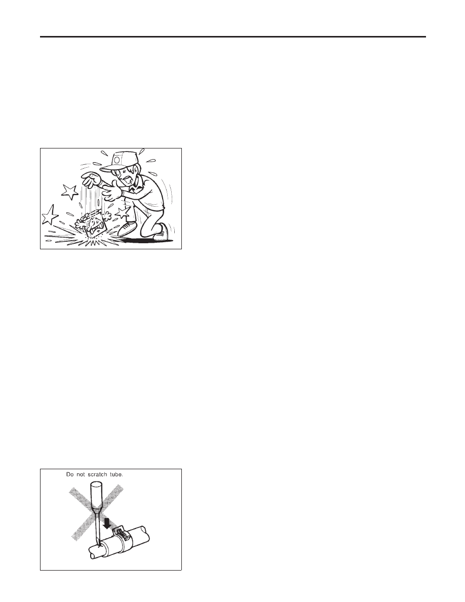
PRECAUTIONS FOR HOSES

NLGI0001S06

Hose Removal and Installation

NLGI0001S0601

I

To prevent damage to rubber hose, do not pry off rubber hose
with tapered tool or screwdriver.

PRECAUTIONS

Precautions (Cont’d)

GI-6

SMA020D

I

To reinstall the rubber hose securely, make sure of hose inser-
tion length and clamp orientation. (If tube is equipped with
hose stopper, insert rubber hose into tube until it butts up
against hose stopper.)

SMA021D

Hose Clamping

NLGI0001S0602

I

If old rubber hose is re-used, install hose clamp in its original
position (at the indentation where the old clamp was). If there
is a trace of tube bulging left on the old rubber hose, align
rubber hose at that position.

I

Discard old clamps; replace with new ones.

SMA022D

I

After installing leaf spring clamps, apply force to them in the
direction of the arrow, tightening rubber hose equally all
around.

PRECAUTIONS FOR ENGINE OILS

NLGI0001S07

Prolonged and repeated contact with used engine oil may cause
skin cancer. Try to avoid direct skin contact with used oil.
If skin contact is made, wash thoroughly with soap or hand cleaner
as soon as possible.

Health Protection Precautions

NLGI0001S0701

I

Avoid prolonged and repeated contact with oils, particularly
used engine oils.

I

Wear protective clothing, including impervious gloves where
practicable.

I

Do not put oily rags in pockets.

I

Avoid contaminating clothes, particularly underclothing, with
oil.

I

Heavily soiled clothing and oil-impregnated footwear should
not be worn. Overalls must be cleaned regularly.

I

First Aid treatment should be obtained immediately for open
cuts and wounds.

I

Use barrier creams, applying them before each work period, to
help the removal of oil from the skin.

I

Wash with soap and water to ensure all oil is removed (skin
cleansers and nail brushes will help). Preparations containing
lanolin replace the natural skin oils which have been removed.

MA

EM

LC

EC

FE

CL

MT

AT

AX

SU

BR

ST

RS

BT

HA

SC

EL

IDX

PRECAUTIONS

Precautions (Cont’d)

GI-7

I

Do not use gasoline, kerosine, diesel fuel, gas oil, thinners or
solvents for cleaning skin.

I

If skin disorders develop, obtain medical advice without delay.

I

Where practicable, degrease components prior to handling.

I

Where there is a risk of eye contact, eye protection should be
worn, for example, chemical goggles or face shields; in addi-
tion an eye wash facility should be provided.

Environmental Protection Precautions

NLGI0001S0702

Burning used engine oil in small space heaters or boilers can be
recommended only for units of approved design. The heating sys-
tem must meet the requirements of HM Inspectorate of Pollution for
small burners of less than 0.4 MW. If in doubt, check with the
appropriate local authority and/or manufacturer of the approved
appliance.
Dispose of used oil and used oil filters through authorized waste
disposal contractors to licensed waste disposal sites, or to the
waste oil reclamation trade. If in doubt, contact the local authority
for advice on disposal facilities.
It is illegal to pour used oil on to the ground, down sewers or drains,
or into water courses.
The regulations concerning the pollution vary between
regions.

PRECAUTIONS FOR FUEL

NLGI0001S08

Gasoline Engine

NLGI0001S0804

Models with three way catalyst
Unleaded premium gasoline of at least 95 octane (RON)
If premium gasoline is not available, unleaded regular gaso-
line with an octane rating of 91 (RON) may be temporarily
used, but only under the following precautions:

I

Have the fuel tank filled only partially with unleaded regu-
lar gasoline, and fill up with premium unleaded gasoline
as soon as possible.

I

Avoid full throttle driving and abrupt acceleration.

CAUTION:

Do not use leaded gasoline. Using leaded gasoline will dam-
age the three way catalyst.

Diesel Engine*:

NLGI0001S0805

Diesel fuel of at least 50 cetane
*

If two types of diesel fuel are available, use summer or winter

fuel properly according to the following temperature conditions.

I

Above −7°C (20°F) ... Summer type diesel fuel.

I

Below −7°C (20°F) ... Winter type diesel fuel.

CAUTION:

I

Do not use home heating oil, gasoline, or other alternate
fuels in your diesel engine. The use of those can cause
engine damage.

I

Do not use summer fuel at temperatures below −7°C
(20°F). The cold temperatures will cause wax to form in the
fuel. As a result, it may prevent the engine from running
smoothly.

I

Do not add gasoline or other alternate fuels to diesel fuel.

PRECAUTIONS FOR AIR CONDITIONING

NLGI0001S09

Use an approved refrigerant recovery unit any time the air condi-
tioning system must be discharged. Refer to ATC-128, “HFC-134a
(R-134a) Service Procedure” for specific instructions.

PRECAUTIONS

Precautions (Cont’d)

GI-8

NLGI0002

I

ALPHABETICAL INDEX is provided at the end of this manual so that you can rapidly find the item and
page you are searching for.

I

A QUICK REFERENCE INDEX, a black tab (e.g.

) is provided on the first page. You can quickly find

the first page of each section by matching it to the section’s black tab.

I

THE CONTENTS are listed on the first page of each section.

I

THE TITLE is indicated on the upper portion of each page and shows the part or system.

I

THE PAGE NUMBER of each section consists of two letters which designate the particular section and a
number (e.g. “BR-5”).

I

THE LARGE ILLUSTRATIONS are exploded views (See below.) and contain tightening torques, lubrica-
tion points, section number of the PARTS CATALOG (e.g. SEC. 440) and other information necessary to
perform repairs.
The illustrations should be used in reference to service matters only. When ordering parts, refer to the
appropriate PARTS CATALOG.

SBR364AC

I

THE SMALL ILLUSTRATIONS show the important steps such as inspection, use of special tools, knacks
of work and hidden or tricky steps which are not shown in the previous large illustrations.
Assembly, inspection and adjustment procedures for the complicated units such as the automatic transaxle
or transmission, etc. are presented in a step-by-step format where necessary.

I

The UNITS given in this manual are primarily expressed as the SI UNIT (International System of Unit),
and alternatively expressed in the metric system and in the yard/pound system.
“Example”

Tightening torque:

59 - 78 N·m (6.0 - 8.0 kg-m, 43 - 58 ft-lb)

I

TROUBLE DIAGNOSES are included in sections dealing with complicated components.

I

SERVICE DATA AND SPECIFICATIONS are contained at the end of each section for quick reference of
data.

I

The following SYMBOLS AND ABBREVIATIONS are used:

MA

EM

LC

EC

FE

CL

MT

AT

AX

SU

BR

ST

RS

BT

HA

SC

EL

IDX

HOW TO USE THIS MANUAL

GI-9

SYMBOL

ABBREVIATION

SYMBOL

ABBREVIATION

Tightening torque

2WD

2-Wheel Drive

Should be lubricated with grease. Unless oth-
erwise indicated, use recommended multi-pur-
pose grease.

A/C

Air Conditioner

Should be lubricated with oil.

P/S

Power Steering

Sealing point

SST

Special Service Tools

Checking point

SAE

Society of Automotive Engineers, Inc.

Always replace after every disassembly.

ATF

Automatic Transmission Fluid

q

P

Apply petroleum jelly.

D

1

Drive range 1st gear

Apply ATF.

D

2

Drive range 2nd gear

Select with proper thickness.

D

3

Drive range 3rd gear

Adjustment is required.

D

4

Drive range 4th gear

SDS

Service Data and Specifications

OD

Overdrive

LH, RH

Left-Hand, Right-Hand

2

2

2nd range 2nd gear

FR, RR

Front, Rear

2

1

2nd range 1st gear

M/T

Manual Transaxle/Transmission

1

2

1st range 2nd gear

A/T

Automatic Transaxle/Transmission

1

1

1st range 1st gear

HOW TO USE THIS MANUAL

GI-10

NLGI0003

Sample/Wiring Diagram — EXAMPL —

NLGI0003S01

I

For Description, refer to GI-13.

SGI091A

MA

EM

LC

EC

FE

CL

MT

AT

AX

SU

BR

ST

RS

BT

HA

SC

EL

IDX

HOW TO READ WIRING DIAGRAMS

Sample/Wiring Diagram — EXAMPL —

GI-11

OPTIONAL SPLICE

NLGI0003S0101

SGI942

HOW TO READ WIRING DIAGRAMS

Sample/Wiring Diagram — EXAMPL — (Cont’d)

GI-12

Description

=NLGI0003S02

Number

Item

Description

1

Power condition

I

This shows the condition when the system receives battery positive voltage (can be
operated).

2

Fusible link

I

The double line shows that this is a fusible link.

I

The open circle shows current flow in, and the shaded circle shows current flow out.

3

Fusible link/fuse loca-
tion

I

This shows the location of the fusible link or fuse in the fusible link or fuse box. For
arrangement, refer to EL-12, “POWER SUPPLY ROUTING”.

4

Fuse

I

The single line shows that this is a fuse.

I

The open circle shows current flow in, and the shaded circle shows current flow out.

5

Current rating

I

This shows the current rating of the fusible link or fuse.

6

Connectors

I

This shows that connector E3 is female and connector M1 is male.

I

The G/R wire is located in the 1A terminal of both connectors.

I

Terminal number with an alphabet (1A, 5B, etc.) indicates that the connector is SMJ con-
nector. Refer to GI-19.

7

Optional splice

I

The open circle shows that the splice is optional depending on vehicle application.

8

Splice

I

The shaded circle shows that the splice is always on the vehicle.

9

Page crossing

I

This arrow shows that the circuit continues to an adjacent page.

I

The A will match with the A on the preceding or next page.

10

Common connector

I

The dotted lines between terminals show that these terminals are part of the same con-
nector.

11

Option abbreviation

I

This shows that the circuit is optional depending on vehicle application.

12

Relay

I

This shows an internal representation of the relay. For details, refer to EL-9, “STAN-
DARDIZED RELAY”.

13

Connectors

I

This shows that the connector is connected to the body or a terminal with bolt or nut.

14

Wire color

I

This shows a code for the color of the wire.

B = Black
W = White
R = Red
G = Green
L = Blue
Y = Yellow
LG = Light Green

BR = Brown
OR = Orange
P = Pink
PU = Purple
GY = Gray
SB = Sky Blue
CH = Dark Brown
DG = Dark Green

When the wire color is striped, the base color is given first, followed by the stripe color as
shown below:
Example: L/W = Blue with White Stripe

15

Option description

I

This shows a description of the option abbreviation used on the page.

16

Switch

I

This shows that continuity exists between terminals 1 and 2 when the switch is in the A
position. Continuity exists between terminals 1 and 3 when the switch is in the B posi-
tion.

17

Assembly parts

I

Connector terminal in component shows that it is a harness incorporated assembly.

18

Cell code

I

This identifies each page of the wiring diagram by section, system and wiring diagram
page number.

19

Current flow arrow

I

Arrow indicates electric current flow, especially where the direction of standard flow (ver-
tically downward or horizontally from left to right) is difficult to follow.

I

A double arrow “

” shows that current can flow in either direction depending on cir-

cuit operation.

MA

EM

LC

EC

FE

CL

MT

AT

AX

SU

BR

ST

RS

BT

HA

SC

EL

IDX

HOW TO READ WIRING DIAGRAMS

Description

GI-13

Number

Item

Description

20

System branch

I

This shows that the system branches to another system identified by cell code (section
and system).

21

Page crossing

I

This arrow shows that the circuit continues to another page identified by cell code.

I

The C will match with the C on another page within the system other than the next or
preceding pages.

22

Shielded line

I

The line enclosed by broken line circle shows shield wire.

23

Component box in
wave line

I

This shows that another part of the component is also shown on another page (indicated
by wave line) within the system.

24

Component name

I

This shows the name of a component.

25

Connector number

I

This shows the connector number.

I

The letter shows which harness the connector is located in.
Example: M: main harness. For detail and to locate the connector, refer to EL-604, “Main
Harness”. A coordinate grid is included for complex harnesses to aid in locating connec-
tors.

26

Ground (GND)

I

The line spliced and grounded under wire color shows that ground line is spliced at the
grounded connector.

27

Ground (GND)

I

This shows the ground connection. For detailed ground distribution information, refer to
EL-23, “GROUND DISTRIBUTION”.

28

Connector views

I

This area shows the connector faces of the components in the wiring diagram on the
page.

29

Common component

I

Connectors enclosed in broken line show that these connectors belong to the same com-
ponent.

30

Connector color

I

This shows a code for the color of the connector. For code meaning, refer to wire color
codes, Number 14 of this chart.

31

Fusible link and fuse
box

I

This shows the arrangement of fusible link(s) and fuse(s), used for connector views of
“POWER SUPPLY ROUTING” in EL section.
The open square shows current flow in, and the shaded square shows current flow out.

32

Reference area

I

This shows that more information on the Super Multiple Junction (SMJ), Electrical Units,
exists at the end of the manual. Refer to GI-19 for details.

HOW TO READ WIRING DIAGRAMS

Description (Cont’d)

GI-14

SGI364

CONNECTOR SYMBOLS

=NLGI0003S0201

Most of connector symbols in wiring diagrams are shown from the
terminal side.

I

Connector symbols shown from the terminal side are enclosed
by a single line and followed by the direction mark.

I

Connector symbols shown from the harness side are enclosed
by a double line and followed by the direction mark.

I

Certain systems and components, especially those related to
OBD, may use a new style slide-locking type harness connec-
tor. For description and how to disconnect, refer to EL-7, “HAR-
NESS CONNECTOR”.

SGI363

I

Male and female terminals
Connector guides for male terminals are shown in black and
female terminals in white in wiring diagrams.

MA

EM

LC

EC

FE

CL

MT

AT

AX

SU

BR

ST

RS

BT

HA

SC

EL

IDX

HOW TO READ WIRING DIAGRAMS

Description (Cont’d)

GI-15

AGI070

HARNESS INDICATION

NLGI0003S0202

I

Letter designations next to test meter probe indicate harness
(connector) wire color.

I

Connector numbers in a single circle M33 indicate harness
connectors.

COMPONENT INDICATION

NLGI0003S0203

I

Connector numbers in a double circle F211 indicate compo-
nent connectors.

SGI860

SWITCH POSITIONS

NLGI0003S0204

Switches are shown in wiring diagrams as if the vehicle is in the
“normal” condition.
A vehicle is in the “normal” condition when:

I

ignition switch is “OFF”,

I

doors, hood and trunk lid/back door are closed,

I

pedals are not depressed, and

I

parking brake is released.

HOW TO READ WIRING DIAGRAMS

Description (Cont’d)

GI-16

SGI862-A

DETECTABLE LINES AND NON-DETECTABLE LINES

NLGI0003S0205

In some wiring diagrams, two kinds of lines, representing wires,
with different weight are used.

I

A line with regular weight (wider line) represents a “detectable
line for DTC (Diagnostic Trouble Code)”. A “detectable line for
DTC” is a circuit in which ECM can detect its malfunctions with
the on board diagnostic system.

I

A line with less weight (thinner line) represents a “non-detect-
able line for DTC”. A “non-detectable line for DTC” is a circuit
in which ECM cannot detect its malfunctions with the on board
diagnostic system.

MA

EM

LC

EC

FE

CL

MT

AT

AX

SU

BR

ST

RS

BT

HA

SC

EL

IDX

HOW TO READ WIRING DIAGRAMS

Description (Cont’d)

GI-17

MULTIPLE SWITCH

=NLGI0003S0206

The continuity of multiple switch is described in two ways as shown
below.

I

The switch chart is used in schematic diagrams.

I

The switch diagram is used in wiring diagrams.

SGI875

HOW TO READ WIRING DIAGRAMS

Description (Cont’d)

GI-18

REFERENCE AREA

=NLGI0003S0207

The Reference Area of the wiring diagram contains references to
additional electrical reference pages at the end of the manual. If
connector numbers and titles are shown in the Reference Area of
the wiring diagram, these connector symbols are not shown in the
Connector Area.

SGI092A

Super multiple junction (SMJ)
In a wiring diagram, the SMJ connectors include a letter of the
alphabet in the terminal number.
SMJ connector numbers are shown in the Reference Area of the
wiring diagram. SMJ terminal arrangement can be found on the
electrical reference pages at the end of the manual. For terminal
arrangement of these connectors, refer to the “SUPER MULTIPLE
JUNCTION (SMJ)” electrical reference page at the end of the

MA

EM

LC

EC

FE

CL

MT

AT

AX

SU

BR

ST

RS

BT

HA

SC

EL

IDX

HOW TO READ WIRING DIAGRAMS

Description (Cont’d)

GI-19

manual.
Fuse block — Junction box (J/B)
Fuse block — Junction box (J/B) connector number is shown in the
Reference Area of the wiring diagram. For connector terminal and
fuse arrangement, refer to the “FUSE BLOCK — Junction Box
(J/B)” electrical reference page at the end of the manual.
Fuse and fusible link box
For fuse arrangement in the fuse and fusible link box, refer to the
“FUSE AND FUSIBLE LINK BOX” electrical reference page at the
end of the manual.
Electrical units
Electrical unit connector symbols are shown in the Connector Area
of the wiring diagram.
However, when there is not enough space to show the connector
terminal arrangement in the Connector Area of the wiring diagram,
the electrical unit connector number is shown in the Reference
Area of the wiring diagram. For electrical unit connector terminal
arrangement, refer to the “ELECTRICAL UNITS” electrical refer-
ence page at the end of the manual. Most of the electrical unit
connectors on this page are shown from the harness side of the
connector.
Joint connector
Joint connector symbols are shown in the connector area of the
wiring diagram. For connector internal wiring layout and joint con-
nector terminal arrangement, refer to the “JOINT CONNECTOR
(J/C)” electrical reference page at the end of the manual.

HOW TO READ WIRING DIAGRAMS

Description (Cont’d)

GI-20

NLGI0005

Work Flow

NLGI0005S01

SGI838

STEP

DESCRIPTION

STEP 1

Get detailed information about the conditions and the environment when the incident occurred.
The following are key pieces of information required to make a good analysis:

WHAT

Vehicle Model, Engine, Transmission and the System (i.e. Radio).

WHEN

Date, Time of Day, Weather Conditions, Frequency.

WHERE

Road Conditions, Altitude and Traffic Situation.

HOW

System Symptoms, Operating Conditions (Other Components Interaction).
Service History and if any After Market Accessories have been installed.

STEP 2

Operate the system, road test if necessary.
Verify the parameter of the incident.
If the incident cannot be duplicated, refer to “Incident Simulation Tests” next page.

STEP 3

Get the proper diagnoses materials together including:
POWER SUPPLY ROUTING
System Operation Descriptions
Applicable Service Manual Sections
Check for any Service Bulletin.
Identify where to begin diagnoses based upon your knowledge of the system operation and the cus-
tomer comments.

STEP 4

Inspect the system for mechanical binding, loose connectors or wiring damage.
Determine which circuits and components are involved and diagnose using the Power Supply Routing
and Harness Layouts.

STEP 5

Repair or replace the incident circuit or component.

STEP 6

Operate the system in all modes. Verify the system works properly under all conditions. Make sure you
have not inadvertently created a new incident during your diagnoses or repair steps.

MA

EM

LC

EC

FE

CL

MT

AT

AX

SU

BR

ST

RS

BT

HA

SC

EL

IDX

HOW TO PERFORM EFFICIENT DIAGNOSES FOR AN ELECTRICAL INCIDENT

Work Flow

GI-21


Content      ..     212      213      214      215     ..