Almera Tino V10 (2003 year). Manual - part 201


  Index      Manuals     Almera Tino V10 (2003 year) - Service and Repair Manual


Search            copyright infringement  


Content      ..     199      200      201      202     ..


Almera Tino V10 (2003 year). Manual - part 201


CYLINDER HEAD

EM-65

[QG]

C

D

E

F

G

H

I

J

K

L

M

A

EM

8.

Install valve collet.

Compress valve spring with valve spring compressor (special
service tool). Install valve collet with magnet hand.

Tap stem edge lightly with plastic hammer after installation to
check its installed condition.

9.

Install adjusting shim (if so equipped) and valve lifter.

10. Install engine coolant temperature sensor.

Apply Genuine Liquid Gasket or equivalent to the thread.

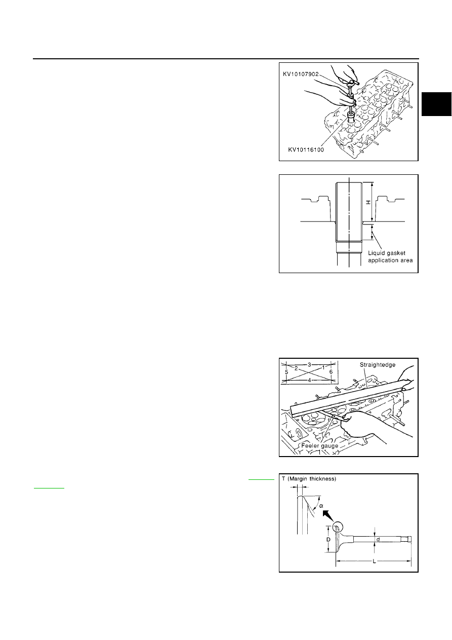
11. Install spark plug tube.

Press-fit spark plug tube following procedure below.

a.

Remove old liquid gasket adhering to cylinder-head mounting
hole.

b.

Apply liquid gasket to area within approximately 15 mm (0.59 in)
from edge of spark plug tube press-fit side.

Use Genuine Liquid Gasket or equivalent.

c.

Using a drift, press-fit spark plug tube so that its height “H” is as
specified in the figure.

CAUTION:

When press-fitting, take care not to deform spark plug tube.

After press-fitting, wipe off liquid gasket protruding onto cylinder-head upper face.

12. Install spark plug with spark plug wrench (commercial service tool).

Inspection After Disassembly

EBS00QEQ

CYLINDER HEAD DISTORTION

1.

Wipe off oil and remove water scale (like deposit), gasket,
sealer, carbon, etc with scraper.

CAUTION:

Use utmost care not to allow gasket debris to enter pas-
sages for oil or water.

2.

At each of several locations on bottom surface of cylinder head,
measure distortion in six directions.

VALVE DIMENSIONS

Check dimensions of each valve. For dimensions, refer to

EM-97,

"VALVE"

.

PBIC1016E

Standard press-fit height “H”:

: 41.0 - 42.0 mm (1.61 - 1.65 in)

KBIA1248E

Limit

: 0.1 mm (0.004 in)

PBIC0075E

SEM188A

EM-66

[QG]

CYLINDER HEAD

VALVE GUIDE CLEARANCE

Perform this inspection before removing valve guide.

1.

Make sure that the valve stem diameter is within the specification.

2.

Push the valve out by approx. 15 mm (0.59 in) toward the combustion chamber side to measure the
valve's run-out volume (in the direction of dial gauge) with dial gauge.

3.

The half of the run-out volume accounts for the valve guide clearance.

VALVE GUIDE REPLACEMENT

When valve guide is removed, replace with oversized [0.2 mm (0.008 in)] valve guide.
1.

To remove valve guide, heat cylinder head to 110 to 130

°

C (230

to 266

°

F) by soaking in heated oil.

2.

Drive out valve guide with a press [under a 20 kN (2 ton, 2.2 US
ton, 2.0 lmp ton) pressure] or hammer and suitable tool.

3.

Ream cylinder head valve guide hole.

Standard

Intake

: 0.020 - 0.050 mm (0.0008 - 0.0020 in)

Exhaust

: 0.040 - 0.070 mm (0.0016 - 0.0028 in)

PBIC0077E

SEM008A

SEM931C

Valve guide hole diameter (for service parts):

Intake and exhaust

: 9.685 - 9.696 mm (0.3813 - 0.3817 in) dia.

SEM932C

CYLINDER HEAD

EM-67

[QG]

C

D

E

F

G

H

I

J

K

L

M

A

EM

4.

Heat cylinder head to 110 to 130

°

C (230 to 266

°

F) by soaking in

heated oil.

5.

Press valve guide from camshaft side to dimensions as in illus-
tration.

CAUTION:

Cylinder head contains heat. When working, wear protec-
tive equipment to avoid getting burned.

6.

Using valve guide reamer, apply reamer finish to valve guide.

VALVE SEAT CONTACT

After confirming that the dimensions of valve guides and valves
are within specifications, perform this procedure.

Apply prussian blue (or white lead) onto contacting surface of
valve seat to check the condition of the valve contact on the sur-
face.

Check if the contact area band is continuous all around the cir-
cumference.

If not, grind to adjust valve fitting and check again. If the contact-
ing surface still has N.G conditions even after the re-check,
replace valve seat.

SEM008A

PBIC0577E

Standard

Intake and exhaust

: 5.500 - 5.515 mm (0.2165 - 0.2171 in) dia.

SEM932C

EMA0487D

EM-68

[QG]

CYLINDER HEAD

VALVE SEAT REPLACEMENT

When valve seat is removed, replace with oversized [0.5 mm (0.020 in)] valve seat.

1.

Bore out old seat until it collapses. Boring should not continue beyond the bottom face of the seat recess
in cylinder head. Set the machine depth stop to ensure this.

2.

Ream cylinder head recess diameter for service valve seat.

Be sure to ream in circles concentric to the valve guide center.

This will enable valve seat to fit correctly.

3.

Heat cylinder head to 110 to 130

°

C (230 to 266

°

F) by soaking in

heated oil.

4.

Provide valve seats cooled well with dry ice. Force fit valve seat
into cylinder head.

CAUTION:

Avoid directly to touching cold valve seats.

Cylinder head contains heat. When working, wear protec-
tive equipment to avoid getting burned.

5.

Using valve seat cutter set (commercial service tool) or valve
seat grinder, finish the seat to the specified dimensions.

CAUTION:

When using valve seat cutter, firmly grip the cutter handle
with both hands. Then, press on the contacting surface all
around the circumference to cut in a single drive. Improper
pressure on with the cutter or cutting many different times
may result in stage valve seat.

Oversize [0.5 mm (0.020 in)]:

Intake: 31.5 mm (1.240 in)

Exhaust: 26.5 mm (1.043 in)

SEM795A

SEM008A

PBIC0579E

SEM934C

CYLINDER HEAD

EM-69

[QG]

C

D

E

F

G

H

I

J

K

L

M

A

EM

Grind to obtain the dimensions indicated in figure.

6.

Using compound, grind to adjust valve fitting.

7.

Check again for normal contact.

VALVE SPRING SQUARENESS

Set try square along the side of valve spring and rotate the spring.

Measure the maximum clearance between the top face of spring and
try square.

VALVE SPRING DIMENSIONS AND VALVE SPRING PRESSURE LOAD

Check valve spring pressure with valve spring seat installed at spec-
ified spring height.

CAUTION:

Do not remove valve spring seat.

Standard:

D1 dia.

: 27.8 - 28.0 mm (1.094 - 1.102 in)

D2 dia.

: 29.5 - 29.7 mm (1.161 - 1.169 in)

D3 dia.

: 31.9 - 32.1 mm (1.256 - 1.264 in)

D4 dia.

: 24.5 - 24.7 mm (0.965 - 0.972 in)

D5 dia.

: 26.2 - 26.4 mm (1.031- 1.039 in)

PBIC0974E

Limit

: 1.8 mm (0.071 in)

PBIC0080E

Standard:

Free height

40.0 mm (1.575 in)

Installation
height

32.82 mm (1.2921 in)

Installation load

147.5 - 166.3 N (15.04 - 16.96 kg,
33.2 - 37.4 lb)

Height during
valve open

23.64 mm (0.9307 in)

Load with valve
open

347.8 - 392.2 N (35.5 - 40.0 kg,
78.2 - 88.2 lb)

SEM113

EM-70

[QG]

ENGINE ASSEMBLY

ENGINE ASSEMBLY

PFP:10001

Removal and Installation

EBS00QER

WARNING:

Situate vehicle on a flat and solid surface.

Place chocks at front and back of rear wheels.

For engines not equipped with engine slingers, attach proper slingers and bolts described in
PARTS CATALOG.

CAUTION:

Always be careful to work safely, avoid forceful or uninstructed operations.

Do not start working until exhaust system and coolant are cool enough.

If items or work required are not covered by the engine main body section, refer to the applicable
sections.

Always use the support point specified for lifting.

Use either 2-pole lift type or separate type lift as best you can. If board-on type is used for
unavoidable reasons, support at the rear axle jacking point with transmission jack or similar tool
before starting work, in preparation for the backward shift of center of gravity.

For supporting points for lifting and jacking point at rear axle, refer to GI-43, “Lifting Points and
Tow Truck Towing”.

NEM346

1.

RH engine mounting

2.

RH engine mounting bracket

3.

LH engine mounting

4.

Rear engine mounting bracket

5.

Rear engine mounting

6.

Dynamic damper (Specific models
only)

7.

center member

8.

Front engine mounting bracket

9.

Front engine mounting

ENGINE ASSEMBLY

EM-71

[QG]

C

D

E

F

G

H

I

J

K

L

M

A

EM

REMOVAL

Description of work
Remove engine and transaxle assembly from under vehicle. Then separate and remove engine.
Preparation

1.

Release fuel pressure. Refer to

EC-52, "FUEL PRESSURE RELEASE"

(WITH EURO-OBD),

EC-579,

"FUEL PRESSURE RELEASE"

(WITHOUT EURO-OBD).

2.

Remove engine hood.

3.

Drain coolant from radiator drain plug.

4.

Remove coolant reservoir tank and bracket.

5.

drain engine oil.

6.

Remove the following parts.

Battery and battery tray

Undercover (with splash cover)

LH/RH front wheel

Drive belt; Refer to

EM-15, "Removal and Installation"

.

Alternator

Idler pulley and bracket Assembly

Air duct and air cleaner case assembly; Refer to

EM-16, "Removal and Installation"

.

Radiator upper hose, lower hose and A/T cooler hose

Radiator and cooling fan

Stabilizer bar

7.

Disconnect engine room harness from the engine side and set it aside for easier work.

Disconnect harness connector of power steering oil pressure sensor.

8.

Disconnect all the body-side hoses (vacuum hose, etc.) and ground at engine side.

Engine room LH

9.

Disconnect fuel feed hoses.

CAUTION:

Install a plug to prevent fuel from draining.

10. Disconnect heater hose, and install plug it to prevent engine coolant from draining.

11. Disconnect select cable from transaxle and move. (A/T vehicle)

Engine room RH

12. Remove air conditioner compressor with piping connected from bracket. Temporarily secure it on body

with a rope to avoid putting load on it.

Vehicle underbody
13. Remove exhaust front tube.

14. Remove power steering pump bracket from cylinder block. Using a rope, temporarily secure it with power

steering pump to vehicle side.

15. Remove ABS wheel sensor and brake caliper. Then fix them on vehicle with rope or similar means.

16. Remove drive shaft from steering knuckle. Refer to AX-11, “Removal”.

17. Disconnect control rod and support rod form transaxle. (M/T vehicle)
Removal

18. Install engine slinger to front left of cylinder head.

NOTE:
For rear side, use those provided on engine.

: 30.4 - 40.2 N·m (3.1 - 4.1 kg-m, 23 - 29 ft-lb)

MBIA0041E

EM-72

[QG]

ENGINE ASSEMBLY

19. Install lifting chain hooks into engine slinger and suspend engine with hoist.

20. Lift with hoist and secure the engine in position.

Use a manual lift table caddy (commercial service tool) or
equivalently rigid tool such as a jack or trestle. Securely sup-
port bottom of engine and transaxle, and simultaneously
adjust hoist tension.

CAUTION:

Put a piece of wood or something similar as the sup-
porting surface, secure a completely stable condition.

21. Remove RH engine mounting insulator.

22. Pull LH engine mounting through-bolt out.

23. Remove mounting bolts at front and rear of center member.

24. Lower manual lift table caddy (or raise lift), and remove engine

transaxle assembly from vehicle.

CAUTION:

When carrying out this work, be sure to check all parts
for interference with vehicle body.

Be sure to check that all the applicable connections have
been properly disconnected.

Be careful to prevent vehicle from dropping off the lift. Be
aware that changes in center of gravity may cause bal-
ance incidents.

Disassembly

The following shows engine and transaxle disassembly on level ground.

CAUTION:

During disassembly, always support bottom with a wooden block. Suspend engine slinger with a
hoist. Be sure to check safety of work at any time.

25. Remove center member.

26. Remove engine mounting insulators and bracket.

27. Remove stater motor. Refer to SC-13, “Starting System”.

28. Separate engine and transaxle.

INSTALLATION

Install in the reverse order of removal.

Do not allow oil to get on mounting insulator. Be careful not to damage mounting insulator.

When installation directions are specified, install parts according to the direction marks on them referring
to components illustration.

Make sure that each mounting insulator is seated properly, and tighten mounting bolts and nuts.

INSPECTION AFTER INSTALLATION

Before starting engine, check the levels of coolant, lubrications and working oils. If less than required
quantity, fill to the specified level.

MBIA0041E

PBIC0583E

KBIA0227J

ENGINE ASSEMBLY

EM-73

[QG]

C

D

E

F

G

H

I

J

K

L

M

A

EM

Use procedure below to check for fuel leakage.
a. Turn ignition switch ON (with engine stopped). With fuel pressure applied to fuel piping, check for fuel
leakage at connection points.
b. Start engine. With engine speed increased, check again for fuel leakage at connection points.

Run engine to check for unusual noise and vibration.

Warm up engine thoroughly to make sure there is no leakage of coolant, lubricants, working oil, fuel and
exhaust gas.

Bleed air from passages in pipes and tubes of applicable lines, such as in cooling system.

After cooling down engine, again check amounts of coolant, lubricants, oil, and fluid. Refill to specified
level, if necessary.

EM-74

[QG]

CYLINDER BLOCK

CYLINDER BLOCK

PFP:11010

Disassembly and Assembly

EBS00QES

MBIA0042E

CYLINDER BLOCK

EM-75

[QG]

C

D

E

F

G

H

I

J

K

L

M

A

EM

CAUTION:

Apply new engine oil to parts marked in illustration before installation.

DISASSEMBLY

1.

Remove engine and transaxle assembly from vehicle, and separate transaxle from engine. Refer to

EM-

70, "Removal and Installation"

.

2.

Mount engine on an engine stand with the following procedure.

a.

Remove exhaust manifold and catalytic converter. Refer to

EM-21, "Removal and Installation"

.

b.

Remove engine front mounting bracket, alternator and air compressor bracket.

c.

Install engine sub-attachment to left side of cylinder block.

d.

Lift engine, and mount it onto the engine stand.

1.

Rear oil seal

2.

Rear oil seal retainer

3.

Crankshaft position sensor (POS)

4.

O-ring

5.

Knock sensor

6.

Oil level gauge guide

7.

Cylinder block

8.

Thrust bearing

9.

Main bearing

10. Crankshaft

11. Key

12. Top ring

13. 2nd ring

14. Oil ring

15. Main bearing

16. Piston

17. Snap ring

18. Piston pin

19. Connecting rod

20. Connecting rod bearing

21. Connecting rod cap

22. Connecting rod nut

23. Main bearing cap bolt

24. Baffle plate

25. Main bearing cap

26. Signal plate

27. Rear plate

28. Coolant drain plug

29. Flywheel (M/T models)

30. Drive plate (A/T models)

PBIC0585E

PBIC1017E

EM-76

[QG]

CYLINDER BLOCK

A commercial engine stand can be used.

NOTE:

This example is an engine stand for holding at transaxle
mounting side with the flywheel or drive plate removed.

3.

Drain engine oil and coolant from inside of engine.

4.

Remove the following components and associated parts.

Fuel tube and injector assembly; Refer to

EM-29, "Removal and Installation"

.

Intake manifold and intake manifold collector assembly; Refer to

EM-18, "Removal and Installation"

.

Ignition coil; Refer to

EM-27, "Removal and Installation"

.

Rocker cover; Refer to

EM-32, "Removal and Installation"

.

Oil pan and oil strainer; Refer to

EM-25, "Removal and Installation"

.

Front cover and timing chain; Refer to

EM-50, "Removal and Installation"

.

Camshaft; Refer to

EM-35, "Removal and Installation"

.

Cylinder head assembly; Refer to

EM-65, "Inspection After Disassembly"

.

Auxiliary brackets and oil filter

5.

Remove knock sensor.

CAUTION:

Avoid impacts such as a dropping.

6.

Remove crankshaft position sensor (POS).

CAUTION:

Avoid impacts such as a dropping.

Do not disassemble.

Keep it away from metal particles.

Do not place sensor close to magnetic materials.

7.

Remove flywheel (M/T models) or drive plate (A/T models). Fix
crankshaft with a ring gear stopper (special service tool), and
remove mounting bolts.

8.

Remove rear plate.

9.

Remove rear oil seal retainer.

Insert a flat-bladed screwdriver between main bearing cap
and rear oil seal retainer to remove retainer.

10. Remove rear oil seal from rear oil seal retainer.

Punch out with a flat-bladed screwdriver.

CAUTION:

Be careful not to damage rear oil seal retainer.

PBIC0085E

PBIC0586E

SEM880F

CYLINDER BLOCK

EM-77

[QG]

C

D

E

F

G

H

I

J

K

L

M

A

EM

11. Remove the piston and connecting rod assembly.

Before removing the piston and connecting rod assembly,
check the connecting rod side clearance. Refer to

EM-88,

"CONNECTING ROD SIDE CLEARANCE"

.

a.

Position the crankshaft pin corresponding to the connecting rod
to be removed onto the bottom dead center.

b.

Remove the connecting rod cap.

c.

Using a hammer handle or similar tool, push the piston and con-
necting rod assembly out to the cylinder head side.

12. Remove the connecting rod bearings.

CAUTION:

When removing them, note the installation position. Keep them in the correct order.

13. Remove the piston rings form the piston.

Before removing the piston rings, check the piston ring side
clearance. Refer to

EM-89, "PISTON RING SIDE CLEAR-

ANCE"

.

Use a piston ring expander (commercial service tool).

CAUTION:

When removing the piston rings, be careful not to dam-
age the piston.

Be careful not to damage piston rings by expanding them
excessively.

14. Remove the piston from the connecting rod as follows:
a.

Using a snap ring pliers, remove the snap ring.

b.

Heat piston to 60 to 70

°

C (140 to 158

°

F) with drier or equivalent.

PBIC0259E

PBIC0087E

PBIC0088E

PBIC0089E

EM-78

[QG]

CYLINDER BLOCK

c.

Push out piston pin with stick of outer diameter approximately 17
mm (0.67 in).

15. Remove main bearing cap bolts.

Loosen main bearing cap bolts in several steps in reverse
order shown in the figure, and remove them.

Measure crankshaft side clearance before loosening main
bearing cap bolts. Refer to

EM-87, "CRANKSHAFT SIDE

CLEARANCE"

.

16. Remove main bearing caps.

Using main bearing cap bolts as shown, remove center main
bearing cap while shaking it back-and-forth.

To remove front and rear main bearing caps, lever them off
using screwdriver or similar tool. Or, using a plastic hammer,
tap them back-and-forth.

CAUTION:

Using shop cloth or wooden block, protect oil pan mount-
ing surface on cylinder block, so that mounting surface is
not damaged.

PBIC0262E

SEM933F

EMD0879D

EMD0222D

CYLINDER BLOCK

EM-79

[QG]

C

D

E

F

G

H

I

J

K

L

M

A

EM

17. Remove crankshaft.

CAUTION:

When placing crankshaft on ground, be careful not to
damage signal plate.

Never remove signal plate unless it is necessary.

NOTE:
If it is removed, positioning dowel pin (dowel pins for crankshaft
and signal plate are specified as a single set) must be rein-
stalled.

18. Remove main bearing and thrust bearing from cylinder block and main bearing cap.

CAUTION:

Check mounting positions, and store them without mixing them up.

19. Remove baffle plate.

ASSEMBLY

1.

Blow air sufficiently through engine coolant passage of cylinder block, oil passage, crank case and cylin-
der bore to remove foreign objects.

2.

Install oil jet for timing chain lubrication.

Face its flat surface upward, and push it as far as it will go.

3.

Install baffle plate.

4.

Install the main bearings and the thrust bearings.

a.

Remove dust, dirt, and oil on the bearing mating surfaces of the
cylinder block and the lower cylinder block.

b.

Install the thrust bearings to the both sides of the No. 3 journal
housing on the cylinder block.

Install the thrust bearings with the oil groove facing the crank-
shaft arm (outside).

c.

Install the main bearings paying attention to the direction.

The main bearing with an oil hole and groove goes on the cyl-
inder block. The one without them goes on the lower cylinder
block.

Main bearings (cylinder block side) for journal No. 1 and for
No. 2 to No. 5 are different.

Before installing the bearings, apply engine oil to the bearing
surface (inside). Do not apply oil to the back surface, but thor-
oughly clean it.

When installing, align the bearing stopper to the notch.

Ensure the oil holes on cylinder block and those on the corre-
sponding bearing are aligned.

SEM928F

PBIC0588E

PBIC0264E

PBIC0590E

EM-80

[QG]

CYLINDER BLOCK

5.

Install the signal plate to the crankshaft.

a.

Position crankshaft and signal plate using a positioning dowel
pin, and tighten mounting bolts.

b.

Remove dowel pin.

CAUTION:

Be sure to remove dowel pin.

NOTE:

Dowel pins of crankshaft and signal plate are provided as a
set for each.

If dowel pin is not available (when crankshaft and signal plate
are reused), use M6 bolt [length under head: 10 mm (0.39 in)
or longer] as its substitute.

6.

Install the crankshaft to the cylinder block.

While turning the crankshaft by hand, check that it turns smoothly.

7.

Install main bearing cap.

Main bearing cap is identified by identification paint No. made
on it before it is removed.

Install it with arrow facing to front.

NOTE:
Main bearing cap cannot be replaced as a single part, because it
is machined together with cylinder block.

8.

Tighten main bearing bolts in several steps in numerical order
shown in the figure.

Apply engine oil onto thread and seat of mounting bolt.

After tightening bolts to specified torque, make sure that
crankshaft rotates smoothly.

Check crankshaft side clearance. Refer to

EM-87, "CRANK-

SHAFT SIDE CLEARANCE"

.

9.

Install piston to connecting rod.

a.

Using snap ring pliers, install snap ring to groove of piston rear side.

Install with chamfered side facing piston pin side. Refer to

EM-74, "Disassembly and Assembly"

.

b.

Install piston to connecting rod.

Using hot-air blower, heat piston to 60 to 70

°

C (140 to 158

°

F) so that piston pin can be easily inserted

by hand. Insert piston pin into piston and connecting rod from front side of piston.

Assemble so that front mark on piston head and oil hole in
connecting rod are positioned as shown in the figure.

c.

Install snap ring to front side of piston.

Refer to step “a” to install snap ring.

After installation, make sure that connecting rod moves
smoothly.

PBIC0265E

SEM420C

SEM933F

PBIC0591E


Content      ..     199      200      201      202     ..