Almera Tino V10 (2003 year). Manual - part 199


  Index      Manuals     Almera Tino V10 (2003 year) - Service and Repair Manual


Search            copyright infringement  


Content      ..     197      198      199      200     ..


Almera Tino V10 (2003 year). Manual - part 199


ROCKER COVER

EM-33

[QG]

C

D

E

F

G

H

I

J

K

L

M

A

EM

6.

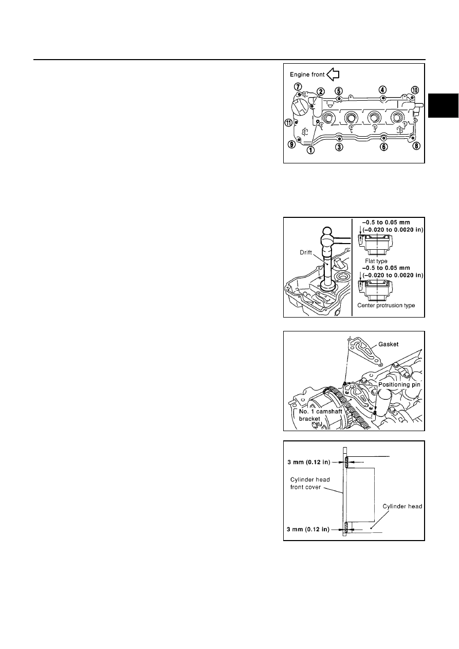
Loosen bolts in reverse order shown in the figure.

7.

If replacement is necessary, remove rocker cover oil seal using flat-head screwdriver.

CAUTION:

Be careful not to damage rocker cover.

INSTALLATION

1.

Install rocker cover oil seal.

Using drift with outer diameter 97 mm (3.82 in) and inner
diameter 83 mm (3.27 in) to 88 mm (3.46 in) (commercial ser-
vice tool), press oil seal in.

NOTE:
There are 2 types of oil seal. If oil seal with flat bottom surface is
pressed in, drift with any inner diameter can be used.

Press oil seal in until it is flush with installation surface.

2.

Install rocker cover in following steps.

a.

Install gasket on top of No. 1 camshaft bracket.

Position gasket aligning its shape with camshaft bracket side.
Align positioning stopper pin with hole on gasket, and install.

b.

Install gasket (for circumference, square type) to installation
groove of rocker cover.

c.

Apply liquid gasket to positions shown in figure, then install
rocker cover.

KBIA1376E

KBIA1377E

KBIA1379E

PBIC0555E

EM-34

[QG]

ROCKER COVER

d.

Tighten mounting screws to specified torque in 2 or more steps
in numerical order shown in figure.

3.

Install intake valve timing control solenoid valve and camshaft position sensor (PHASE).

Tighten bolt after fully inserting it into rocker cover.

4.

Install PCV valve.

Insert until flange contacts grommet tightly.

5.

Install remaining parts in the reverse order of removal.

Bolt length:

Bolt position

25 mm (0.98 in)

: 1

65 mm (2.56 in)

: 2

20 mm (0.79 in)

: Except the above (all circumference)

KBIA1376E

CAMSHAFT

EM-35

[QG]

C

D

E

F

G

H

I

J

K

L

M

A

EM

CAMSHAFT

PFP:13001

Removal and Installation

EBS00QEH

CAUTION:

Prior to installation, apply engine oil to the parts marked in the figure.

REMOVAL

1.

Remove rocker cover. Refer to

EM-32, "Removal and Installation"

.

2.

Remove cylinder head front cover.

Move harness secured to front surface beforehand.

3.

Set No. 1 cylinder at TDC of its compression stroke.

a.

Remove RH splash cover (integrated with undercover).

b.

Rotate crankshaft pulley clockwise and align yellow paint mark
with timing indicator.

PBIC0965E

1.

Camshaft bracket

2.

Camshaft sprocket (INT)

3.

Camshaft sprocket (EXH)

4.

Washer

5.

Cylinder head front cover

6.

Chain tensioner

7.

Valve lifter

8.

Adjusting shim (If so equipped)

9.

Camshaft (EXH)

10. Camshaft (INT)

MBIB0193E

EM-36

[QG]

CAMSHAFT

c.

Confirm mating marks stamped on intake and exhaust sprockets
are located as shown.

If not, rotate crankshaft pulley as shown and align them.

d.

Referring to mating marks on intake and exhaust camshaft
sprockets, put paint mating marks on timing chain links.

4.

Set intake camshaft sprocket to most advanced position.

CAUTION:

Removal/installation of intake camshaft sprocket is required to maintain most advanced position
because of following reasons. Therefore, follow procedure exactly.

Sprocket and vane (camshaft in front) rotate and become
offset within specific angle range.

When engine is stationary, vane is located at most
retarded position. Vane is fixed to sprocket by internal
lock pin. Therefore, it does not rotate.

If camshaft sprocket mounting bolts are turned under
above circumstance, lock pin will be damaged by lateral
load (shear stress). It may cause non-standard operation.

Set intake camshaft sprocket to most advanced position as
follows.

NOTE:
“Rotating direction” means direction viewed from engine front side.

CAUTION:

Do not remove chain tensioner before performing this step.

a.

Using a wrench, hold hexagonal part so that intake camshaft
does not move.

b.

Using an air gun, apply air pressure to intake valve timing con-
trol solenoid valve advanced side oil passage on top surface of
No. 1 camshaft bracket.

Keep applying air pressure until step “d” is completed.

CAUTION:

Be careful not to damage oil passage from interference of
air gun tip.

Thoroughly wipe off oil before applying air pressure.
When applying air pressure, cover around air gun using a rag. Wear protective glasses if neces-
sary.

MBIB0194E

MBIB0195E

MBIB0196E

Compression pressure

: 300 kPa (3.00 bar, 3.06 kg/cm

2

, 43.5 psi) or more

MBIB0197E

CAMSHAFT

EM-37

[QG]

C

D

E

F

G

H

I

J

K

L

M

A

EM

c.

Slowly turn intake camshaft in direction A (counterclockwise:
intake manifold side).

Perform while applying air pressure.

CAUTION:

Be careful not to dislocate camshaft retaining spanner.

d.

During above step, operating click (a sound indicating internal
lock pin is disengaged) is heard from inside of intake camshaft
sprocket. After hearing it, slowly turn intake camshaft in direction
B (clockwise: exhaust manifold side), and set to most advanced
position.

Perform while applying air pressure.

When vane rotates solely against sprocket, lock pin is disengaged even if operating click is not heard.

If lock pin is not disengaged, apply vibration by jiggling the camshaft with a spanner.

If lock pin is not disengaged with above step, hit intake camshaft in front by using plastic hammer.

e.

The following status indicates that most advanced position is
achieved: vane starts rotating on its own, then sprocket also
starts rotating when camshaft is turned. When above status is
achieved, this step is complete.

Most advanced position is confirmed when stopper pin groove
and lock pin breathing groove are aligned.

f.

Stop air, insert stopper pin [approximately 3 mm (0.12 in) dia.,
length of inserted part is approximately 15 mm (0.59 in)]

into

pinhole on camshaft sprocket to fix most advanced position.

NOTE:
In the figure, an Allen wrench [a/f 2.5 mm (0.091 in), short part:
approximately 20 mm (0.79 in), long part: approximately 50 mm
(1.97 in)] is used for stopper pin as an example.

CAUTION:

Load (spring reaction force) is not applied to stopper pin.
Pin is easily detached. Therefore, secure it with vinyl tape to
prevent detachment.

5.

Remove chain tensioner.

Remove in the following order.

a.

Press plate down, and release stopper tab.

b.

Insert plunger into tensioner body until it stops.

c.

Secure plate by passing stopper pin (such as a hard wire)
through plate hole and body hole. (Plunger is also secured.)

d.

Remove mounting bolts, and remove chain tensioner.

KBIA1414J

MBIB0198E

PBIC0966E

MBIB0201E

EM-38

[QG]

CAMSHAFT

6.

While holding hexagonal part of camshaft with a spanner, loosen
mounting bolts and remove intake and exhaust camshaft
sprockets.

CAUTION:

Be careful that tool does not interfere with A/C piping.

Avoid securing camshaft at other than hexagonal part
and loosening mounting bolts by utilizing tension of tim-
ing chain.

Handle intake camshaft sprocket, taking care of following.

CAUTION:

Secure stopper pin with vinyl tape to prevent detach-
ment.

Avoid dropping it or subjecting it to impact.

Do not disassemble. (Do not loosen 3 bolts on front sur-
face.)

NOTE:
If stopper pin is detached and lock pin is engaged at most retarded position during removal, recover as
follows.

a.

Reinstall stopper pin to intake camshaft, and tighten intake camshaft sprocket mounting bolts so that air
does not leak.

CAUTION:

Tightening torque for mounting bolts must be minimum so that air does not leak, preventing dam-
age on internal lock pin.

b.

Apply air pressure to disengage lock pin, and turn vane to most advanced position. (This step can be per-
formed with timing chain removed.)

c.

Reinstall stopper pin.

d.

Remove intakecamshaft sprocket from camshaft.

7.

Remove camshaft brackets.

Loosen mounting bolts in several steps in reverse order
shown in figure.

8.

Remove camshaft.

CAUTION:

Be careful not to damage signal plate on rear end of intake
camshaft and crankshaft.

9.

Remove adjusting shims and valve lifters.

Identify installation position of each valve. Arrange removed
valves so they cannot be mixed up.

INSTALLATION

1.

Install valve lifters and adjusting shims.

Install them in their original positions.

Install adjusting shim with its stamped mark facing downward (valve lifter side).

EMD0826D

MBIB0202E

PBIC0969E

CAMSHAFT

EM-39

[QG]

C

D

E

F

G

H

I

J

K

L

M

A

EM

2.

Install camshaft.

Intake and exhaust camshafts are distinguished by checking
difference between front and rear end shapes.

NOTE:
Some exhust camshafts have a groove on the rear end.

Install camshafts so that dowel pins on their front ends are
positioned as shown.

3.

Install camshaft brackets.

Completely remove any foreign material on back surfaces of
camshaft brackets and top surface of cylinder head.

Referring to marks on top surfaces of camshaft brackets,
install them to their original positions and in their original
directions.

4.

Tighten camshaft bracket mounting bolts as follows:

a.

Different bolts are used depending on installation location. Refer
to following and install appropriate bolts.

b.

First tighten bolts 9 through 12, then tighten bolts 1 through 8 in
numerical order.

c.

Tighten in numerical order shown in figure.

d.

Tighten again in numerical order shown in figure.

5.

Install intake camshaft sprocket as follows.

Before installation, make sure that stopper pin is inserted in intake camshaft sprocket.

NOTE:
Service parts are provided with pin inserted.

MBIB0204E

PBIC0967E

MBIB0206E

Bolt color :

1 to 10 in figure

: black (reamer bolt)

11 and 12 in figure

: gold

: 2.0 N·m (0.2 kg-m, 18 in-lb)

: 5.9 N·m (0.6 kg-m, 52 in-lb)

: 9.0 - 11.8 N·m (0.92 - 1.2 kg-m, 80 - 104 in-lb)

PBIC0969E

EM-40

[QG]

CAMSHAFT

CAUTION:

Stopper pin is easily detached. Secure it with vinyl tape to prevent detachment.

a.

Install timing chain by aligning its mating mark (marked when
timing chain is removed) with mark on camshaft sprocket.

Align dowel pin on camshaft front surface and pinhole on
sprocket backside, then install.

b.

While holding hexagonal part of camshaft with a spanner,
tighten intake camshaft sprocket mounting bolts.

Make sure that stopper pin is not detached.

6.

Install exhaust camshaft sprocket as follows.

a.

Install timing chain by aligning its mating mark (marked when
timing chain is removed) with mark on camshaft sprocket.

Align dowel pin on camshaft front surface and pinhole on
sprocket, then install.

b.

While holding hexagonal part of camshaft with a spanner,
tighten exhaust camshaft sprocket mounting bolts.

NOTE:
Tightening torque is different from intake side tightening torque.

c.

Make sure that mating marks on intake/exhaust camshaft
sprockets and mating mark on timing chain are aligned.

7.

Install chain tensioner.

Hold plate and plunger with a stopper pin, then install them.

After installation, remove stopper pin and release plunger.

Make sure again that mating marks on intake/exhaust cam-
shaft sprockets and mating mark on timing chain are aligned.

MBIB0208E

MBIB0209E

MBIB0210E

MBIB0211E

CAMSHAFT

EM-41

[QG]

C

D

E

F

G

H

I

J

K

L

M

A

EM

8.

Remove stopper pin from intake camshaft sprocket.

9.

Slowly turn crankshaft pulley clockwise to set intake camshaft
sprocket to most retarded position.

Sprocket begins turning after crankshaft does. Once sprocket
starts turning, keep turning crankshaft until the vane (cam-
shaft) also begins turning. Most retarded position should now
be achieved.

Most retarded position is confirmed when stopper pin groove
is at a clockwise offset from lock pin breathing groove.

While turning crankshaft slightly more counterclockwise, con-
firm that lock pin is engaged when vane and sprocket turn
together.

10. Install cylinder head front cover.

Apply liquid gasket (Use Genuine Liquid Gasket or equiva-
lent) continuously as shown in figure.

Install it by aligning dowel pin on cylinder head.

11. Check and adjust valve clearance. Refer to

EM-44, "Valve Lifter

Clearance"

.

12. From this step, install in the reverse order of removal.

PBIC0966E

MBIB0213E

MBIB0214E

PBIC0968E

EM-42

[QG]

CAMSHAFT

INSPECTION AFTER REMOVAL
Camshaft Runout

Place a V-block on a surface plate to support No. 2 and No. 5
journals on camshaft.

CAUTION:

Do not support No. 1 journal (camshaft sprocket mounting
side), because its diameter is different from that of the other
4 journals.

Set a dial gauge vertically onto journal No. 3.

Rotate the camshaft in one direction by hand and read indication
on the gauge.

A half of reading value is actual bend.

Camshaft Cam Height

Measure with a micrometer.

Camshaft Journal Clearance

Outer Diameter of Camshaft Journal

Measure with a micrometer.

Inner Diameter of Camshaft Bracket

Tighten camshaft bracket bolts to the specified torque.

Using an inside micrometer, measure inner diameter of the cam-
shaft bracket.

Calculation of Camshaft Journal Clearance
(Oil clearance) = (Camshaft bracket inner diameter) - (Camshaft journal outer diameter)

Standard

: 0.02 mm (0.0008 in) or less

MBIB0215E

Intake

: 40.217 - 40.407 mm (1.5833 - 1.5908 in)

Exhaust

: 39.205 - 39.395 mm (1.5435 - 1.5510 in)

MBIB0216E

Standard

No. 1

: 27.935 - 27.955 mm (1.0998 - 1.1006 in) dia.

No. 2 to No. 5

: 23.935 - 23.955 mm (0.9423 - 0.9431 in) dia.

MBIB0217E

Standard

No. 1

: 28.000 - 28.021 mm (1.1024 - 1.1032 in) dia.

No. 2 to No. 5

: 24.000 - 24.021 mm (0.9449 - 0.9457 in) dia.

MBIB0218E

CAMSHAFT

EM-43

[QG]

C

D

E

F

G

H

I

J

K

L

M

A

EM

If outside the standard, refer to standard of each unit part and replace camshaft or cylinder head as appro-
priate.

NOTE:
Camshaft bracket is machined with cylinder head. Replace them as cylinder head assembly.

Camshaft End play

Position a dial gauge onto front end of camshaft in thrust direc-
tion. Read indication of dial gauge while moving camshaft back
and forth (axial direction).

If outside the standard, replace camshaft with new one. Then
measure it again.

If still outside the standard, replace cylinder head with new one.

Camshaft Sprocket Runout

Using a dial gauge, measure camshaft sprocket runout.

Valve Lifter and Adjusting Shim (Shim type)

Check surfaces of valve lifter and shim for cracks and wear.

Valve Lifter Clearance

Outer Diameter of Valve Lifter

Standard

: 0.045 - 0.086 mm (0.0018 - 0.0028 in)

Standard

Intake

: 0.070 - 0.143 mm (0.0028 - 0.0056 in)

Exhaust

: 0.115 - 0.188 mm (0.0045 - 0.0074 in)

MBIB0219E

Limit:

Intake

: 0.2 mm (0.008 in)

Exhaust

: 0.15 mm (0.0059 in)

PBIC0930E

SEM160D

EM-44

[QG]

CAMSHAFT

Measure outer diameter with a micrometer.

Valve Lifter Hole Diameter

Using an inside micrometer, measure valve lifter hole diameter
on cylinder head.

Calculation of Valve Lifter Clearance
(Clearance) = (Valve lifter hole inner diameter) - (Valve lifter outer diameter)

If outside the standard, refer to standard of each OD and hole ID and then replace valve lifter or cylinder
head as appropriate.

Valve Lifter (Shimless type)

Check if surface of valve lifter has any wear or cracks.

Valve Lifter Clearance

Outer Diameter of Valve Lifter

Measure outer diameter of valve lifter.

Standard

: 29.960 - 29.975 mm (1.1795 - 1.1801 in) dia.

MBIB0220E

Standard

: 30.000 - 30.021 mm (1.1811 - 1.1819 in) dia.

MBIB0221E

Standard

: 0.025 - 0.061 mm (0.0010 - 0.0024 in)

KBIA0182E

Valve lifter outer diameter (Intake and exhaust)

: 29.960 - 29.975 mm (1.1795 - 1.1801 in) dia.

JEM798G

CAMSHAFT

EM-45

[QG]

C

D

E

F

G

H

I

J

K

L

M

A

EM

Valve Lifter Hole Diameter

Using inside micrometer, measure diameter of valve lifter hole of
cylinder head.

Calculation of Valve Lifter Clearance
(Valve lifter clearance) = (hole diameter of valve lifter) – (outer diam-
eter of valve lifter).

When out of specified range, referring to each specification of outer and inner diameter, replace either or
both valve lifter and cylinder head.

Valve Clearance

EBS00QEI

INSPECTION

The following procedure is applicable when: Components related to camshafts or valves are removed,
installed, or replaced. Drivability concerns (poor starting, poor idling, noise) are caused by valve clearance
aging.

1.

Warm up engine, and stop.

2.

Remove RH splash cover (integrated with undercover).

3.

Remove rocker cover. Refer to

EM-32, "Removal and Installation"

.

4.

Turn crankshaft pulley clockwise (viewed from front) to align yel-
low paint with timing indicator.

5.

At this point, confirm that both intake and exhaust cam noses on
No. 1 cylinder face outward. (No. 1 cylinder is at TDC of its com-
pression stroke.)

If not, turn crankshaft pulley more.

NOTE:
Or, valves to be checked when No. 4 cylinder is at TDC of its
compression stroke can be checked first following step 8.

6.

Referring to figure, measure valve clearances of valves with

×

in

table below using a thickness gauge.

Standard (Intake and exhaust)

: 30.000 - 30.021 mm (1.1811 - 1.1819 in) dia.

Standard (Intake and exhaust)

: 0.025 - 0.061 mm (0.0010 - 0.0024 in)

SEM867E

MBIB0222E

Cylinder

No.1

No.2

No.3

No.4

Valve

INT

EXH

INT

EXH

INT

EXH

INT

EXH

No. 1 cylinder at
TDC of its compres-
sion stroke

×

×

×

×

MBIB0223E

MBIB0224E

EM-46

[QG]

CAMSHAFT

*: Approximately 20

°

C (68

°

F) (Reference data)

7.

Turn crankshaft pulley a full turn to position No. 4 cylinder at TDC of its compression stroke.

8.

Referring to figure, measure valve clearance of parts with

×

in

table below.

9.

If outside the standard, adjust applicable valves as shown
below.

ADJUSTMENT (SHIMLESS TYPE)

Perform adjustment depending on selected head thickness of valve lifter.

The specified valve lifter thickness is the dimension at normal temperatures. Ignore dimensional differ-
ences caused by temperature. Use the specifications for hot engine condition to adjust.

1.

Remove camshaft. Refer to

EM-35, "Removal and Installation"

.

2.

Remove the valve lifters at the locations that are outside the standard.

3.

Measure the center thickness of the removed valve lifters with a
micrometer.

4.

Use the equation below to calculate valve lifter thickness for replacement.

Valve lifter thickness calculation:
Thickness of replacement valve lifter = t1+ ( C1 - C2 )
t1 = Thickness of removed valve lifter
C1 = Measured valve clearance
C2=Standard valve clearance:

Valve clearance standard:

Hot

Intake

: 0.304 - 0.416 mm (0.012 - 0.016 in)

Exhaust

: 0.348 - 0.472 mm (0.014 - 0.019 in)

Cold*

Intake

: 0.25 - 0.33 mm (0.010 - 0.013 in)

Exhaust

: 0.32 - 0.40 mm (0.013 - 0.016 in)

If an adjustment is done with cold engine, confirm reference values with hot engine are met.

Limit values with hot engine (reference)

Intake

: 0.21 - 0.47 mm (0.008 - 0.019 in)

Exhaust

: 0.30 - 0.56 mm (0.012 - 0.022 in)

Cylinder

No.1

No.2

No.3

No.4

Valve

INT

EXH

INT

EXH

INT

EXH

INT

EXH

No. 4 cylinder at TDC of
its compression stroke

×

×

×

×

MBIB0225E

KBIA0057E

Intake

: 0.36 mm (0.014 in)

Exhaust

: 0.37 mm (0.015 in)

CAMSHAFT

EM-47

[QG]

C

D

E

F

G

H

I

J

K

L

M

A

EM

Thickness of a new valve lifter can be identified by stamp
marks on the reverse side (inside the cylinder).
Stamp mark 696 indicates 6.96 mm (0.2740 in) in thickness.

Available thickness of valve lifter: 26 sizes with range 6.96 to 7.46 mm (0.2740 to 0.2937 in) in steps of 0.02
mm (0.0008 in) (when manufactured at factory).

5.

Install the selected valve lifter.

6.

Install camshaft.

7.

Manually turn crankshaft pulley a few turns.

8.

Check that valve clearances for cold engine are within specifications by referring to the specified values.

9.

After completing the repair, check valve clearances again with the specifications for warmed engine. Make
sure the values are within specifications.

Valve clearance:

Unit: mm (in)

*: Approximately 20

°

C (68

°

F)

ADJUSTMENT (SHIM TYPE)

Remove adjusting shim for valves with incorrect valve clearance by following the procedure below:

1.

Using a rag, completely wipe off engine oil from surroundings of adjusting shim.

2.

When removing adjusting shim from a cam, turn crankshaft
clockwise (viewed from front) to make cam nose face straight
up.

3.

Turn valve lifter and adjusting shim to removal direction.

Using a slotted screwdriver with extra-thin tip, turn valve lifter
cutout in direction shown by the arrow.

4.

Using camshaft pliers (special service tool), pinch camshaft.
Turn tool up in direction shown by the arrow with camshaft being
a fulcrum. This will push down adjusting shim to allow valve
spring to be compressed.

CAUTION:

Be careful not to damage camshaft and cylinder head.

Be careful not to damage surroundings of valve lifter.

PBIC1077E

Cold* (reference data)

Hot

Intake

0.24 - 0.32 (0.009 - 0.013)

0.32 - 0.40 (0.013 - 0.016)

Exhaust

0.26 - 0.34 (0.010 - 0.013)

0.33 - 0.41 (0.013 - 0.016)

MBIB0226E

KBIA1391J

EM-48

[QG]

CAMSHAFT

5.

With valve spring compressed, securely place tip of lifter stopper
(special service tool) onto surroundings of valve spring. Then
remove camshaft pliers (special service tool).

CAUTION:

If camshaft pliers are suddenly turned back, lifter stopper
may contact and damage camshaft journals. Turn back
camshaft pliers carefully to remove.

6.

Keep adjusting shim slightly up from valve lifter.

Insert a slotted screwdriver with extra-thin tip into cutout on
valve lifter for this purpose.

7.

Using a magnetic handle, remove adjusting shim.

8.

Using a micrometer, measure thickness (t1) of removed adjust-
ing shim at camshaft contact face (around center).

9.

Use following formula to select proper replacement adjusting shim.

Formula to calculate adjusting shim thickness (unit: mm)
Thickness of replacement valve lifter = t1+ ( C1 - C2 )
t1 = Thickness of removed valve lifter
C1 = Measured valve clearance
C2=Standard valve clearance:

PBIC1013E

PBIC1014E

MBIB0229E

Hot engine:

Intake

: 0.37 mm (0.015 in)

Exhaust

: 0.40 mm (0.016 in)

Reference values with cold engine:

Intake

: 0.30 mm (0.012 in)

Exhaust

: 0.35 mm (0.014 in)


Content      ..     197      198      199      200     ..