Almera Tino V10 (2003 year). Manual - part 202


  Index      Manuals     Almera Tino V10 (2003 year) - Service and Repair Manual


Search            copyright infringement  


Content      ..     200      201      202      203     ..


Almera Tino V10 (2003 year). Manual - part 202


CYLINDER BLOCK

EM-81

[QG]

C

D

E

F

G

H

I

J

K

L

M

A

EM

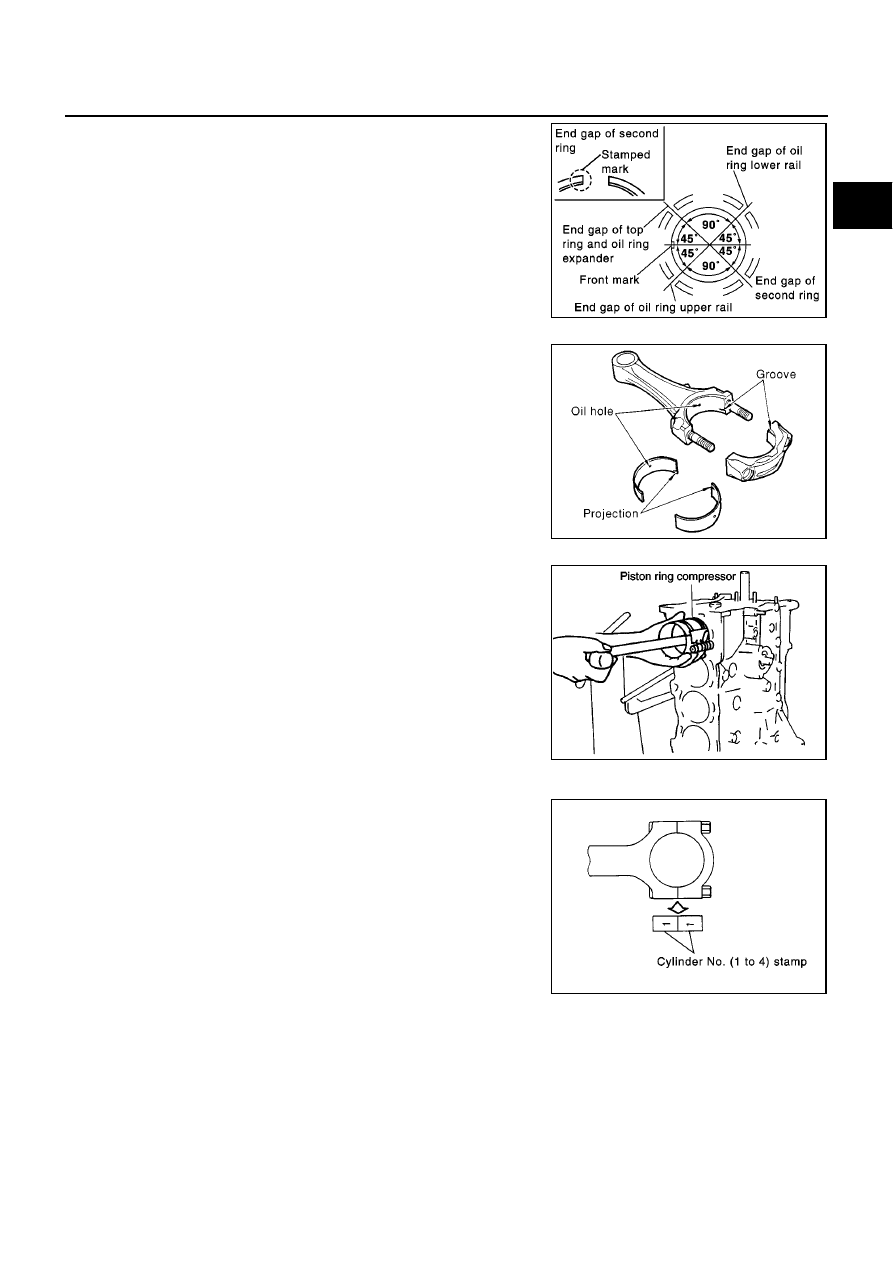
10. Install piston rings with piston ring expander (commercial ser-

vice tool).

CAUTION:

Be careful not to damage piston.

When installing top ring, be careful not to break end gap
step.

Position end gaps of each piston ring to piston front mark as
shown in figure, then install rings.

Install top ring with stamp mark side facing upward.

11. Install the connecting rod bearings to the connecting rod and the

connecting rod cap.

When installing the connecting rod bearings, apply engine oil
to the bearing surface (inside). Do not apply oil to the back
surface, but thoroughly clean it.

When installing, align the connecting rod bearing stopper pro-
trusion with the notch of the connecting rod to install.

Check the oil holes on the connecting rod and those on the
corresponding bearing are aligned.

12. Install the piston and connecting rod assembly to the crankshaft.

Position the crankshaft pin corresponding to the connecting
rod to be installed onto the bottom dead center.

Apply engine oil sufficiently to the cylinder bore, piston and
crankshaft pin.

Match the cylinder position with the cylinder No. on the con-
necting rod to install.

Using a piston ring compressor, install the piston with the front
mark on the piston crown facing the front of the engine.

CAUTION:

Be careful not to damage the crankshaft pin, resulting from
an interference of the connecting rod big end.

13. Install the connecting rod cap.

Match the stamped cylinder number marks on the connecting
rod with those on the cap to install.

PBIC0977E

PBIC0482E

PBIC0267E

PBIC0593E

EM-82

[QG]

CYLINDER BLOCK

14. Tighten connecting rod nuts with the following procedure.

a.

Lubricate connecting rod bolts and seat of nuts with new engine
oil.

b.

Tighten to a torque of 13.72 - 15.68 N·m (1.4 - 1.5 kg-m, 10.2 -
11.5 ft-lb)

c.

Turn all nuts another 35 to 40 degrees (Target: 35 degrees).

CAUTION:

Always use angle wrench (special service tool). Avoid tight-
ening based on visual check alone.

After tightening nuts, make sure that crankshaft rotates
smoothly.

Check connecting rod side clearance. Refer to

EM-88, "CONNECTING ROD SIDE CLEARANCE"

.

15. Install rear oil seal.

Use an oil seal drift (commercial service tool) to press it in. At
this time, be careful not to cause any scratches or burrs on
circumference of oil seal.

Press oil seal into rear oil seal retainer until it does not project
from end.

16. Install rear oil seal retainer.

Apply continuous bead of liquid gasket to parts shown in fig-
ure.

Install rear oil seal retainer by aligning it with dowel pins on
cylinder block.

17. Install rear plate.

SEM943F

SEM897A

PBIC0589E

AEM248

CYLINDER BLOCK

EM-83

[QG]

C

D

E

F

G

H

I

J

K

L

M

A

EM

18. Install flywheel or drive plate.

Install drive plate in direction shown in figure.

Fix crankshaft with ring gear stopper (special service tool).

Tighten mounting bolts diagonally in several steps.

19. Install oil level gauge guide.

Press it in with punch mark for installing instruction in direction
shown in figure.

Apply locking agent to pressed position.

20. Install knock sensor.

Install sensor with connector facing lower right by 45

°

as

shown.

CAUTION:

If any impact by dropping is applied to the knock sensor,
replace it with new one.

Make sure that there is no foreign material on the cylin-
der block mating surface and the back surface of the
knock sensor.

Do not tighten the mounting bolts while holding the con-
nector.

Make sure that the knock sensor does not interfere with other parts.

21. Install crankshaft position sensor (POS).

Tighten bolt after fully inserting crankshaft position sensor (POS) into cylinder block.

22. Tighten accessory brackets to the following tightening torque.

23. Assemble in the reverse order of disassembly.

PBIC0595E

MBIA0043E

Power steering pump bracket:

: 16.7 - 23.5 N·m (1.7 - 2.4 kg-m, 13 - 17 ft-lb)

Alternator air conditioner compressor bracket:

: 29.4 - 34.3 N·m (3.0 - 3.5 kg-m, 22 - 25 ft-lb)

PBIC0597E

EM-84

[QG]

CYLINDER BLOCK

How to Select Piston and Bearing

EBS00QET

DESCRIPTION

*For the service parts, the grade for fitting cannot be selected between a piston pin and a connecting rod.

(Only 0 grade is available.) The information at the shipment from the plant is described as a reference.

The identification grade stamped on each part is the grade for the dimension measured in new condition.
This grade cannot apply to reused parts.

For reused or repaired parts, measure the dimension accurately. Determine the grade by comparing the
measurement with the values of each selection table.

For details of the measurement method of each part, the reuse standards and the selection method of the
selective fitting parts, refer to the text.

HOW TO SELECT PISTON
When New Cylinder Block is Used

Check the cylinder bore grade (1,2 or 3) on rear lower surface of
cylinder block, and select a piston of the same grade.

When Cylinder Block is Reused

1.

Measure the cylinder block bore inner diameter.

Selection points

Selection parts

Selection items

Selection methods

Between cylinder block to
crankshaft

Main bearing

Main bearing grade (bearing
thickness)

Determined by match of cylin-
der block bearing housing
grade (inner diameter of hous-
ing) and crankshaft journal
grade (outer diameter of jour-
nal)

Between crankshaft to connect-
ing rod

Connecting rod bearing

Connecting rod bearing grade
(bearing thickness)

Connecting rod bearing grade
= crankshaft pin grade (outer
diameter of pin). No grade
exists for inner diameter to con-
necting rod large end.

Between cylinder block to pis-
ton

Piston and piston pin assembly
The piston is available together
with piston pin as an assembly.

Piston grade (piston outer
diameter)

Piston grade = cylinder bore
grade (inner diameter of bore)

*Between piston to connecting
rod

PBIC0598E

YEM056

CYLINDER BLOCK

EM-85

[QG]

C

D

E

F

G

H

I

J

K

L

M

A

EM

2.

Determine the bore grade by comparing the measurement with the values under the cylinder bore inner
diameter of the “Piston Selection Table”. Select the piston of the same grade.

Piston Selection Table

Unit: mm (in)

CAUTION:

No stamp mark is only applied to piston side.

NOTE:

The piston is available together with piston pin as an assembly.

The piston pin (piston pin bore) grade is provided only for the parts installed at the plant. For service parts,
no grades can be selected. (Only 0 grade is available.)

HOW TO SELECT CONNECTING ROD BEARING
When New Connecting Rod and Crankshaft are Used

Compare the pin diameter grade (0, 1 or 2) of the crankshaft on
front surface with the values of the selection table of connecting
rod bearing.

NOTE:
There is no grading for connecting rod big end.

When Crankshaft and Connecting Rod are Reused

1.

Confirm connecting rod big end inner diameter is within the standard.

2.

Measure the pin outer diameter of the crankshaft.

3.

Find measured dimension in “Crankshaft pin outer diameter” column in selective-fit service parts table,
and select connecting rod bearing of same grade number.

Connecting Rod Bearing Selection Table

Unit: mm (in)

Grade number (Mark)

1

2 (or no punching)

3

Inner diameter of cylinder bore

80.000 - 80.010

(3.1496 - 3.1500)

80.010 - 80.020

(3.1500 - 3.1504)

80.020 - 80.030

(3.1504 - 3.1508)

Outer diameter of piston

79.965 - 79.975

(3.1482 - 3.1486)

79.975 - 79.985

(3.1486 - 3.1490)

79.985 - 79.995

(3.1490 - 3.1494)

PBIC0606E

Connecting rod big end ID

43.000 - 43.013 (1.6929 - 1.6934)

Crankshaft pin OD

Grade (punched)

0 (no punching)

39.968 - 39.974

(1.5735 - 1.5738)

0

Bearing grade No.

Bearing thickness

Oil clearance

Identification color

STD 0

1.503 - 1.506 (0.0592 - 0.0593)
0.014 - 0.039 (0.0006 - 0.0015)

Black

39.962 - 39.968

(1.5733 - 1.5735)

1

Bearing grade No.

Bearing thickness

Oil clearance

Identification color

STD 1

1.506 - 1.509 (0.0593 - 0.0594)
0.014 - 0.039 (0.0006 - 0.0015)

Red

39.956 - 39.962

(1.5731 - 1.5733)

2

Bearing grade No.

Bearing thickness

Oil clearance

Identification color

STD 2

1.509 - 1.512 (0.0594 - 0.0595)
0.014 - 0.039 (0.0006 - 0.0015)

Green

EM-86

[QG]

CYLINDER BLOCK

Undersize Bearings Usage Guide

When the specified oil clearance is not obtained with standard size connecting rod bearings, use under-
size (US) bearings.

When using undersize bearing, measure the bearing inner diameter with bearing installed, and grind the
crankshaft pin so that the oil clearance satisfies the standard.

Bearing undersize table

Unit: mm (in)

CAUTION:

In grinding the crankshaft pin to use undersize bearings, keep
the fillet R (All crankshaft pins).

HOW TO SELECT MAIN BEARING
When New Cylinder Block and Crankshaft are Used

1.

Apply main bearing housing grade (0, 1 or 2) on bottom of cylin-
der block banks to row in main bearing selection table.

2.

Apply journal diameter grade (0, 1 or 2) on crankshaft front to
column in main bearing selection table.

3.

Select main bearing (STD 0 - 4) at the point where selected row
and column meet in following main bearing selection table.

When Cylinder Block and Crankshaft are Reused

1.

Measure dimension of main bearing housing on cylinder block.

2.

Find measured dimension in “Cylinder block main bearing housing inner diameter” row in following main
bearing selection table.

3.

Measure crankshaft journal diameter.

4.

Find measured dimension in “Crankshaft journal outer diameter” column in following main bearing selec-
tion table.

5.

Select main bearing (STD 0 - 4) at the point where selected row and column meet in following main bear-
ing selection table.

Size

Thickness

US 0.08 (0.0031)

1.542 - 1.546 (0.0607 - 0.0609)

US 0.12 (0.0047)

1.562 - 1.566 (0.0615 - 0.0617)

US 0.25 (0.0098)

1.627 - 1.631 (0.0641 - 0.0642)

PBIC0491E

PBIC0598E

PBIC0607E

CYLINDER BLOCK

EM-87

[QG]

C

D

E

F

G

H

I

J

K

L

M

A

EM

Main Bearing Selection Table

Unit: mm (in)

Use Undersize Bearing Usage Guide

Use undersize (US) bearing when oil clearance with standard size main bearing is not within specification.

When using undersize (US) bearing, measure the bearing inner diameter with bearing installed, and grind
journal until oil clearance falls within specification.

Bearing undersize table

Unit: mm (in)

CAUTION:

Keep fillet R when grinding crankshaft journal in order to use
undersize bearing (All journals).

Inspection After Disassembly

EBS00QEU

CRANKSHAFT SIDE CLEARANCE

Using a dial gauge, measure the clearance between the thrust
bearings and the crankshaft arm when the crankshaft is moved
fully forward or backward.

If the measured value exceeds the limit, replace the thrust bear-
ings, and measure again. If it still exceeds the limit, replace the
crankshaft also.

Connecting block main bearing housing ID

53.644 - 53.652

(2.1120 - 2.1123)

53.652 - 53.660

(2.1123 - 2.1126)

53.660 - 53.668

(2.1126 - 2.1129)

Crankshaft journal

OD

Grade

(punched)

0

1

2

49.956 - 49.964

(1.9668 - 1.9671)

0

Bearing grade No.

Bearing thickness

Oil clearance

Identification color

STD 0

1.826 - 1.830

(0.0719 - 0.0720)

0.020 - 0.044

(0.0008 - 0.0017)

Black

STD 1

1.830 - 1.834

(0.0720 - 0.0722)

0.020 - 0.044

(0.0008 - 0.0017)

Red

STD 2

1.834 - 1.838

(0.0722 - 0.0724)

0.020 - 0.044

(0.0008 - 0.0017)

Green

49.948 - 49.956

(1.9665 - 1.9668)

1

Bearing grade No.

Bearing thickness

Oil clearance

Identification color

STD 1

1.830 - 1.834

(0.0720 - 0.0722)

0.020 - 0.044

(0.0008 - 0.0017)

Red

STD 2

1.834 - 1.838

(0.0722 - 0.0724)

0.020 - 0.044

(0.0008 - 0.0017)

Green

STD 3

1.838 - 1.842

(0.0724 - 0.0725)

0.020 - 0.044

(0.0008 - 0.0017)

Yellow

49.940 - 49.948

(1.9661 - 1.9665)

2

Bearing grade No.

Bearing thickness

Oil clearance

Identification color

STD 2

1.834 - 1.838

(0.0722 - 0.0724)

0.020 - 0.044

(0.0008 - 0.0017)

Green

STD 3

1.838 - 1.842

(0.0724 - 0.0725)

0.020 - 0.044

(0.008 - 0.0017)

Yellow

STD 4

1.842 - 1.846

(0.0725 - 0.0727)

0.020 - 0.044

(0.0008 - 0.0017)

Blue

Size

Thickness

US 0.25 (0.0098)

1.960 - 1.964 (0.0722 - 0.0773)

US 0.50 (0.0197)

2.085 - 2.089 (0.0821 - 0.0822)

PBIC0491E

Standard

: 0.060 - 0.260 mm (0.0024 - 0.0102 in)

Limit

: 0.3 mm (0.012 in)

PBIC0608E

EM-88

[QG]

CYLINDER BLOCK

CONNECTING ROD SIDE CLEARANCE

Measure side clearance between connecting rod and crankshaft
arm with feeler gauge.

If the measured value exceeds the limit, replace the connecting
rod bearings, and measure again. If it still exceeds the limit,
replace the crankshaft also.

PISTON AND PISTON PIN CLEARANCE
Inner Diameter of Piston Pin

Measure the inner diameter of piston pin bore with an inside
micrometer.

Outer Diameter of Piston Pin

Measure outer diameter of piston pin with a micrometer.

Piston and Piston Pin Clearance

(Piston pin clearance) = (Piston pin bore diameter) – (Outer diameter of piston pin)

If clearance exceeds specification, replace either or both of piston/piston pin assembly and connecting rod
assembly with reference to specification of each parts.

Refer to piston selection table to replace piston/piston pin assembly,

EM-84, "HOW TO SELECT PISTON"

.

NOTE:

Regarding marks on piston head, refer to

EM-84, "HOW TO SELECT PISTON"

.

Standard

: 0.200 - 0.470 mm (0.0079 - 0.0185 in)

Limit

: 0.5 mm (0.020 in)

PBIC0609E

Standard

: 18.993 - 18.999 mm (0.7478 - 0.7480 in)

PBIC0116E

Standard

: 18.989 - 19.001 mm (0.7476 - 0.7481 in)

PBIC0117E

Standard:

0.002 - 0.006 mm (0.0001 - 0.0002 in)

CYLINDER BLOCK

EM-89

[QG]

C

D

E

F

G

H

I

J

K

L

M

A

EM

Piston pin hole (piston pin) grade are provided only for the parts
installed at the plant. For service parts, no grades can be
selected. (Only 0 grade is available.)

PISTON RING SIDE CLEARANCE

Measure side clearance of piston ring and piston ring groove
with feeler gauge.

If out of specification, replace piston and/or piston ring assembly.

PISTON RING END GAP

Check if inner diameter of cylinder bore is within specification.
Refer to

EM-92, "PISTON TO CYLINDER BORE CLEARANCE"

.

Insert piston ring until middle of cylinder with piston, and mea-
sure gap.

If out of specification, replace piston ring. If gap still exceeds the limit even with a new ring, re-bore cylin-
der and use oversized piston and piston ring.

PBIC0591E

Standard:

Top ring

: 0.040 - 0.080 mm (0.0016 - 0.0031 in)

2nd ring

: 0.030 - 0.070 mm (0.0012 - 0.0028 in)

Oil ring

: 0.045 - 0.155 mm (0.0018 - 0.0061 in)

Limit:

Top ring

: 0.110 mm (0.0043 in)

2nd ring

: 0.100 mm (0.0039 in)

PBIC0610E

Standard:

Top ring

: 0.20 - 0.39 mm (0.0079 - 0.0154 in)

2nd ring

: 0.32 - 0.56 mm (0.0126 - 0.0220 in)

Oil ring

: 0.20 - 0.69 mm (0.0079 - 0.0272 in)

Limit:

Top ring

: 0.54 mm (0.0213 in)

2nd ring

: 0.67 mm (0.0264 in)

Oil ring

: 0.95 mm (0.0374 in)

SEM822B

EM-90

[QG]

CYLINDER BLOCK

CONNECTING ROD BEND AND TORSION

Check with connecting rod aligner.

If it exceeds the limit, replace connecting rod assembly.

CONNECTING ROD BEARING (BIG END)

Install the connecting rod cap without the connecting rod bearing
installed. After tightening the connecting rod bolt to the specified
torque, measure the connecting rod big end inner diameter
using an inside micrometer.

CONNECTING ROD BUSHING OIL CLEARANCE (SMALL END)
Inner Diameter of Connecting Rod (Small End)

Measure inner diameter of bushing.

Bend:

Limit: 0.15 mm (0.0059 in) per 100 mm (3.94 in) length

Torsion:

Limit: 0.30 mm (0.0118 in) per 100 mm (3.94 in) length

SEM038F

SEM003F

Standard

: 43.000 - 43.013 mm (1.6929 - 1.6934 in) dia.

PBIC0119E

Standard

: 19.000 - 19.012 mm (0.7480 - 0.7485 in) dia.

PBIC0120E

CYLINDER BLOCK

EM-91

[QG]

C

D

E

F

G

H

I

J

K

L

M

A

EM

Outer Diameter of Piston Pin

Measure outer diameter of piston pin.

Connecting Rod Bushing Oil Clearance (Small End)

(Connecting rod small end oil clearance) = (Inner diameter of connecting rod small end) – (Outer diameter of
piston pin)

If the measured value exceeds the standard, replace the connecting rod assembly and/or piston and pis-
ton pin assembly.

If replacing the piston and piston pin assembly, refer to the “Piston Selection Table” to select the piston
corresponding to the applicable bore grade of the cylinder block to be used. Refer to

EM-84, "HOW TO

SELECT PISTON"

.

Factory installed parts grading:

Service parts apply only to grade 0.

Unit: mm (in)

CYLINDER BLOCK DISTORTION

Using a scraper, remove gasket on the cylinder block surface,
and also remove oil, scale, carbon, or other contamination.

CAUTION:

Be careful not to allow gasket flakes to enter the oil or cool-
ant passages.

Measure the distortion on the block upper face at some different
points in 6 directions.

If out of the distortion limit, replace the cylinder block.

Standard

: 18.989 - 19.001 mm (0.7476 - 0.7481 in)

PBIC0117E

Standard

: 0.005 - 0.017 mm (0.0002 - 0.0007 in)

Grade

0

1

Connecting rod small end
inner diameter

19.000 - 19.006

(0.7480 - 0.7483)

19.006 - 19.012

(0.7483 - 0.7485)

Piston pin outer diameter

18.989 - 18.995

(0.7476 - 0.7478)

18.995 - 19.001

(0.7478 - 0.7481)

Piston pin hole diameter

18.993 - 18.996

(0.7478- 0.7479)

18.996 - 18.999

(0.7479 - 0.7480)

PBIC0591E

Limit

: 0.1 mm (0.004 in)

PBIC0121E

EM-92

[QG]

CYLINDER BLOCK

INNER DIAMETER OF MAIN BEARING HOUSING

Install the main bearing caps with the main bearings removed,
and tighten the mounting bolts to the specified torque.

Using a bore gauge, measure the inner diameter of the main
bearing housing.

If out of the standard, replace the cylinder block and lower cylin-
der block assembly.

NOTE:
These components cannot be replaced as a single unit because
they were processed together.

PISTON TO CYLINDER BORE CLEARANCE
Inner Diameter of Cylinder Bore

Using a bore gauge, measure cylinder bore for wear, out-of-
round and taper at 6 different points on each cylinder. (X and Y
directions at A, B and C) (Y is in longitudinal direction of engine)

If the measured value exceeds the limit, or if there are scratches
and/or seizure on the cylinder inner wall, hone or rebore the inner wall.

An oversize piston is provided. When using an oversize piston, rebore the cylinder so that the clearance
of the piston cylinder satisfies the standard.

Outer Diameter of Piston

Measure piston skirt diameter.

Standard

: 53.644 - 53.668 mm (2.1120 - 2.1129 in) dia.

PBIC0611E

PBIC0612E

Standard inner diameter:

80.000 - 80.030 mm (3.1496 - 3.1508 in) dia.

Wear limit:

0.2 mm (0.008 in)

Out-of-round (Difference between X and Y):

0.015 mm (0.0006 in)

Taper limit (Difference between A and C):

0.01 mm (0.0004 in)

Oversize (OS)

: 0.25 mm (0.0098 in)
: 0.5 mm (0.0197 in)

PBIC0613E

Measuring
point

: 42.3 mm (1.665 in) below piston head
upper edge

Standard

: 79.965 - 79.995 mm (3.1482 - 3.1494 in)
dia.

PBIC0125E

CYLINDER BLOCK

EM-93

[QG]

C

D

E

F

G

H

I

J

K

L

M

A

EM

Piston to Cylinder Bore Clearance

Calculate by outer diameter of piston skirt and inner diameter of cylinder (direction X, position B).

(Clearance) = (Inner diameter of cylinder) – (Outer diameter of piston skirt).

If it exceeds the standard, replace piston/piston pin assembly.

Reboring Cylinder Bore

1.

Cylinder bore size is determined by adding piston-to-bore clearance to piston diameter “A”.

2.

Install main bearing caps, and tighten to the specified torque. Otherwise, cylinder bores may be distorted
in final assembly.

3.

Cut cylinder bores.

When any cylinder needs boring, all other cylinders must also be bored.

Do not cut too much out of cylinder bore at a time. Cut only 0.05 mm (0.0020 in) or so in diameter
at a time.

4.

Hone cylinders to obtain specified piston-to-bore clearance.

5.

Measure finished cylinder bore for out-of-round and taper.

Measurement should be done after cylinder bore cools down.

OUTER DIAMETER OF CRANKSHAFT JOURNAL

Measure outer diameter of crankshaft journals.

OUTER DIAMETER OF CRANKSHAFT PIN

Measure outer diameter of crankshaft pin.

OUT-OF-ROUND AND TAPER OF CRANKSHAFT

Using a micrometer, measure the dimensions at 4 different
points shown in the figure on each journal and pin.

Out-of-round is indicated by the difference in dimensions
between A and B at 1 and 2.

Taper is indicated by the difference in dimension between 1 and
2 at A and B.

Standard

: 0.025 - 0.045 mm (0.010 - 0.018 in)

Rebored size calculation: D = A + B - C

where,

D: Bored diameter

A: Piston diameter as measured

B: Piston - to - bore clearance (standard value)

C: Honing allowance 0.02 mm (0.0008 in)

Standard

: 49.940 - 49.964 mm (1.9661 - 1.9671 in) dia.

Standard

: 39.956 - 39.974 mm (1.5731 - 1.5738 in) dia.

PBIC0270E

Limit:

Out-of-round (A – B)

: 0.005 mm (0.0002 in)

Taper (1 – 2)

: 0.005 mm (0.0002 in)

PBIC0614E

EM-94

[QG]

CYLINDER BLOCK

CRANKSHAFT RUNOUT

Place a V-block on a precise flat table to support the journals on
the both end of the crankshaft.

Place a dial gauge straight up on the No. 3 journal.

While rotating the crankshaft, read the movement of the pointer
on the dial gauge. (Total indicator reading)

OIL CLEARANCE OF CONNECTING ROD BEARING
Method of Measurement

Install the connecting rod bearings to the connecting rod and the
cap, and tighten the connecting rod bolts to the specified torque.
Using a inside micrometer measure the inner diameter of con-
necting rod bearing.

(Oil clearance) = (Inner diameter of connecting rod bearing) – (Outer
diameter of crankshaft pin)

If clearance cannot be adjusted within the standard, grind crank-
shaft pin and use undersized bearing. Refer to

EM-85, "HOW

TO SELECT CONNECTING ROD BEARING"

.

Method of Using Plastigage

Remove oil and dust on the crankshaft pin and the surfaces of
each bearing completely.

Cut a plastigage slightly shorter than the bearing width, and
place it in crankshaft axial direction, avoiding oil holes.

Install the connecting rod bearings to the connecting rod cap,
and tighten the connecting rod bolts to the specified torque.

CAUTION:

Never rotate the crankshaft.

Remove the connecting rod cap and bearings, and using the
scale on the plastigage bag, measure the plastigage width.

NOTE:
The procedure when the measured value exceeds the limit is same as that described in the method by
calculation.

OIL CLEARANCE OF MAIN BEARING
Method of Measurement

Install the main bearings to the cylinder block and bearing cap. Measure the main bearing inner diameter
with the bearing cap bolt tightened to the specified torque.

(Oil clearance) = (Inner diameter of main bearing) – (Outer diameter of crankshaft journal)

If the measured value exceeds the limit, select main bearings referring to the main bearing inner diameter
and crankshaft journal outer diameter, so that the oil clearance satisfies the standard. Refer to

EM-86,

"HOW TO SELECT MAIN BEARING"

.

Limit:

: 0.05 mm (0.002 in)

PBIC0271E

Standard

: 0.014 - 0.039 mm (0.0006 - 0.0015 in)

Limit

: 0.1 mm (0.004 in)

PBIC0119E

EM142

Standard

: 0.020 - 0.044 mm (0.0008 - 0.0017 in)

Limit

: 0.1 mm (0.004 in)

CYLINDER BLOCK

EM-95

[QG]

C

D

E

F

G

H

I

J

K

L

M

A

EM

Method of Using Plastigage

Remove oil and dust on the crankshaft journal and the surfaces
of each bearing completely.

Cut a plastigage slightly shorter than the bearing width, and
place it in crankshaft axial direction, avoiding oil holes.

Tighten the main bearing bolts to the specified torque.

CAUTION:

Never rotate the crankshaft.

Remove the bearing cap and bearings, and using the scale on
the plastigage bag, measure the plastigage width.

NOTE:
The procedure when the measured value exceeds the limit is
same as that described in “the method by calculation.”

CRUSH HEIGHT OF MAIN BEARING

When the bearing cap is removed after being tightened to the
specified torque with main bearings installed, the tip end of bear-
ing must protrude.

If the standard is not met, replace main bearings.

FLYWHEEL RUNOUT

Measure deflection of contact surface with dial gauge.

EM142

Standard

: There must be crush height

SEM502G

Flywheel (M/T models)

Limit

: 0.1 mm (0.004 in)

SEM931F

EM-96

[QG]

SERVICE DATA AND SPECIFICATIONS (SDS)

SERVICE DATA AND SPECIFICATIONS (SDS)

PFP:00030

Standard and Limit

EBS00QEV

GENERAL SPECIFICATIONS

INTAKE MANIFOLD AND EXHAUST MANIFOLD

Unit: mm (in)

DRIVE BELTS

Unit: mm (in)

Classification

Gasoline

Cylinder arrangement

4, in-line

Displacement

cm

3

(cu in)

1,769 (107.94)

Bore and stroke

mm (in)

80.0 x 88.0

(3.150 x 3.465)

Valve arrangement

DOHC

Firing order

1-3-4-2

Number of piston rings

Compression

2

Oil

1

Number of main bearings

5

Compression ratio

9.5

Compression pressure

kPa (bar, kg/cm

2

, psi) / 350 rpm

Standard

1,324 (13.24, 135, 192)

Minimum

1,128 (11.28, 11.5, 164)

Differential limit between cylinders

98 (0.98, 1.0, 14)

Valve timing
(Intake valve timing control - OFF)

Unit: degree

a

b

c

d

e

f

208

228

8

56

2

30

PBIC0187E

Limit

Surface distortion

Intake manifold

0.1 (0.004)

Exhaust manifold

0.3 (0.012)

Deflection adjustment

Used belt

New belt

Limit

After adjustment

Alternator

Without air conditioner compressor

10.2 (0.402)

6.5 - 7.0

(0.256 - 0.276)

5.5 - 6.1

(0.217 - 0.240)

With air conditioner compressor

8.1 (0.319)

5.3 - 5.7

(0.209 - 0.224)

4.5 - 5.0

(0.177 - 0.197)

Power steering oil pump

7.1 (0.280)

4.4 - 4.9

(0.173 - 0.193)

3.9 - 4.4

(0.154 - 0.173)

Applied pushing force

98 N (10 kg, 22 lb)


Content      ..     200      201      202      203     ..