Almera Tino V10 (2003 year). Manual - part 163
4
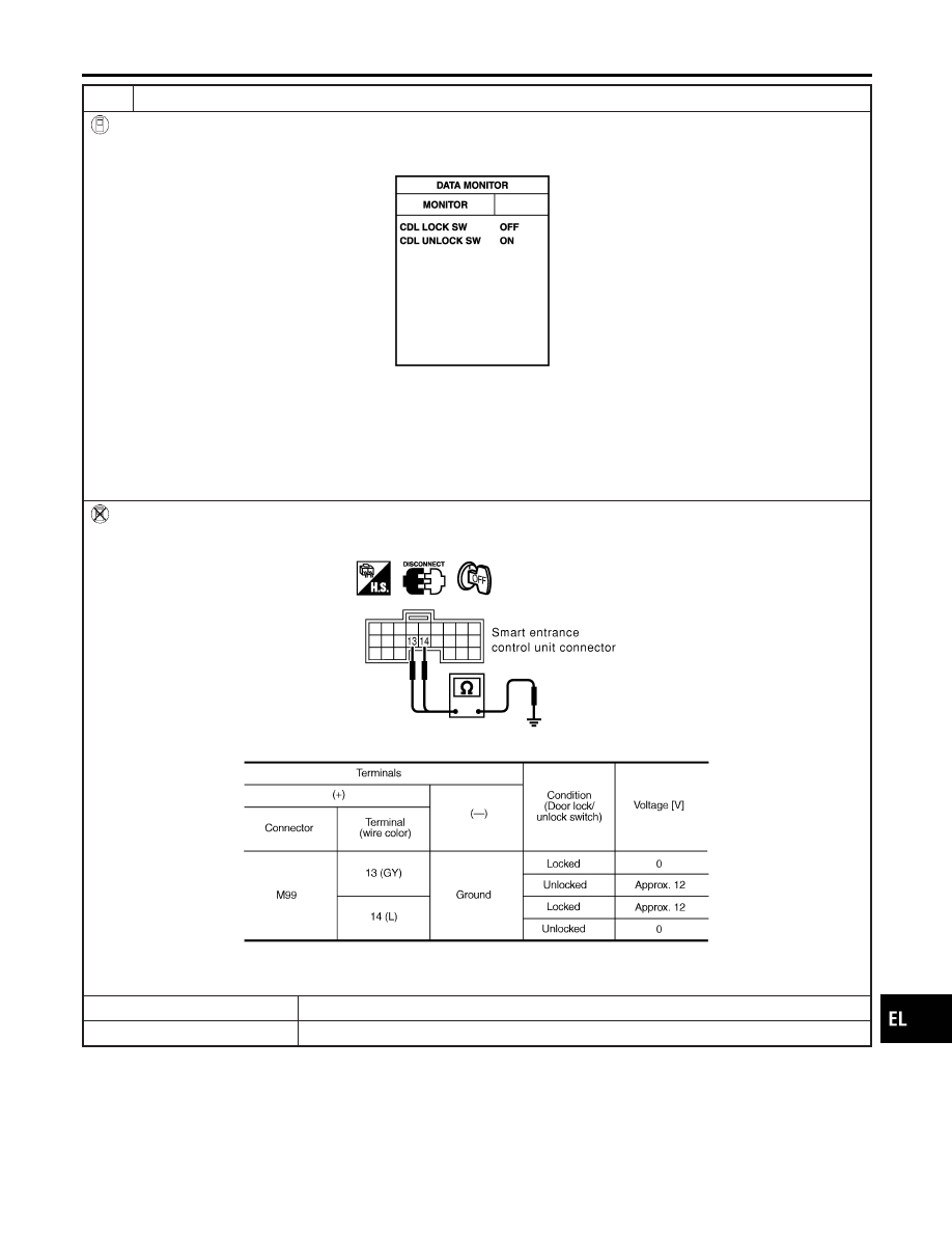
CHECK DOOR LOCK/UNLOCK SWITCH
WITH CONSULT-II
Check door lock/unlock switch signal (“CDL LOCK SW” or “CDL UNLOCK SW”) in “DATA MONITOR” mode with CON-
SULT-II.
MKIB0198E
When door lock/unlock is locked:
CDL LOCK SW ON
CDL UNLOCK SW OFF
When door lock/unlock is unlocked:
CDL LOCK SW OFF
CDL UNLOCK SW ON
WITHOUT CONSULT-II
Check voltage between smart entrance control unit harness connector M99 terminals 13 (GY), 14 (L) and ground.
SIIA1567E
MTBL1639
OK or NG
OK
©
Replace smart entrance control unit.
NG
©
GO TO 5.
GI
MA
EM
LC
EC
FE
CL
MT
AT
AX
SU
BR
ST
RS
BT
HA
SC
IDX
INTERIOR ROOM LAMP
Trouble Diagnoses (Cont’d)
EL-97