Almera Tino V10 (2003 year). Manual - part 162
 

  Index      Manuals     Almera Tino V10 (2003 year) - Service and Repair Manual


Search            copyright infringement  


Content      ..     160      161      162      163     ..


Almera Tino V10 (2003 year). Manual - part 162


YEL951D

GI

MA

EM

LC

EC

FE

CL

MT

AT

AX

SU

BR

ST

RS

BT

HA

SC

IDX

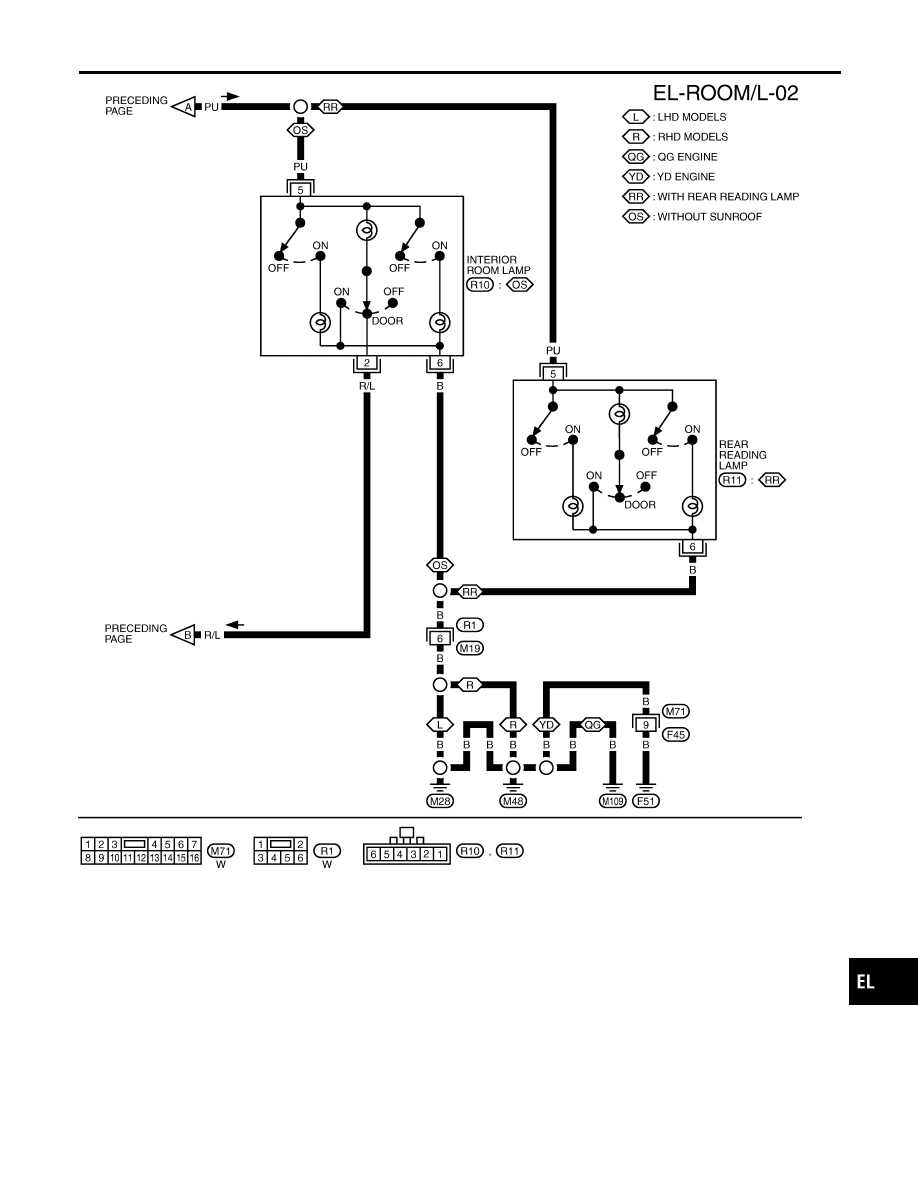
INTERIOR ROOM LAMP

Wiring Diagram — ROOM/L — (Cont’d)

EL-81

YEL952D

INTERIOR ROOM LAMP

Wiring Diagram — ROOM/L — (Cont’d)

EL-82

Terminal and Reference Valve for Smart
Entrance Control Unit

NLEL0680

Terminal

No.

Wire

color

Connections

Operated condition

Voltage (Approximate values)

5

B/R

Key switch

Ignition key Removed

,

Inserted

0V

,

12V

13

GY

Door lock/unlock switches

Neutral

,

Locks

12V

,

0V

14

L

Door lock/unlock switches

Neutral

,

Unlocks

12V

,

0V

28

R/Y

Interior room lamp

When interior lamp is operated using
remote controller (Lamp switch in
“DOOR” position)

12V

,

0V

29

Y/G

Ignition key switch

Ignition key is in “ON” position

12V

43

R/W

Front door switch

Front door (Driver side):
Open

,

Closed

12V

,

0V

44

L/OR

Front door switch
(Passenger side)

Front door (Passenger side):
Open

,

Closed

0V

,

12V

53

B

Ground

0V

56

R/B

Power source

12V

GI

MA

EM

LC

EC

FE

CL

MT

AT

AX

SU

BR

ST

RS

BT

HA

SC

IDX

INTERIOR ROOM LAMP

Terminal and Reference Valve for Smart Entrance Control Unit

EL-83

MBIB0906E

CONSULT-II Inspection Procedure

=NLEL0681

“ROOM LAMP”
1.

Turn ignition switch “OFF”.

2.

Connect “CONSULT-II” to the data link connector.

MBIB0233E

3.

Turn ignition switch “ON”.

4.

Touch “START (NISSAN BASED VHCL)”.

YEL322E

5.

Touch “SMART ENTRANCE”.

YEL324E

6.

Touch “ROOM LAMP”.

SEL788W

7.

Select diagnosis mode.
“DATA MONITOR” are available for “ROOM LAMP”.

INTERIOR ROOM LAMP

CONSULT-II Inspection Procedure

EL-84

CONSULT-II Application Items

NLEL0682

ROOM LAMP
Data Monitor Mode

Item (CONSULT-II screen terms)

Diagnosed system

IGNITION SW

Indicates [ON/OFF] condition of ignition switch.

KEY IN DETECT

Indicates [ON/OFF] condition of electronic key switch.

DOOR SW DR RR

Indicates [ON/OFF] condition of rear door switch (driver side).

DOOR SW AS RR

Indicates [ON/OFF] condition of rear door switch (passenger side).

AS DOOR SW

Indicates [ON/OFF] condition of front door switch (passenger side).

DR DOOR SW

Indicates [ON/OFF] condition of front door switch (driver side).

CDL LOCK SW

Indicates [ON/OFF] condition of door lock/unlock switch (lock signal).

CDL UNLOCK SW

Indicates [ON/OFF] condition of door lock/unlock switch (unlock signal).

RKE LOCK

Indicates [ON/OFF] condition of lock signal from remote controller.

RKE UNLOCK

Indicates [ON/OFF] condition of unlock signal from remote controller.

RKE SEL UNLOCK

Indicates [ON/OFF] condition of select unlock signal from remote controller.

KEY CYL LK

Indicates [ON/OFF] condition of lock signal from door key cylinder.

KEY CYL UNLK

Indicates [ON/OFF] condition of unlock signal from door key cylinder.

GI

MA

EM

LC

EC

FE

CL

MT

AT

AX

SU

BR

ST

RS

BT

HA

SC

IDX

INTERIOR ROOM LAMP

CONSULT-II Application Items

EL-85

Trouble Diagnoses

=NLEL0533

DIAGNOSTIC PROCEDURE 1

NLEL0533S04

Symptom: Interior room lamp timer does not operate

NLEL0533S0401

1

CHECK IGNITION ON SIGNAL

WITH CONSULT-II

Check ignition switch ON signal (“IGNITION SW”) in “DATA MONITOR” mode with CONSULT-II.

MKIB0196E

When ignition switch is ON: IGNITION SW ON
When ignition switch is OFF: IGNITION SW OFF

WITHOUT CONSULT-II

1. Disconnect smart entrance control unit.
2. Check voltage between smart entrance control unit harness connector M100 terminal 29 (Y/G) and ground.

MKIB0072E

MTBL1635

OK or NG

OK

©

GO TO 2.

NG

©

Check the following.

I

10A fuse [No. 10, located in fuse block (J/B)]

I

Harness for open or short between smart entrance control unit and fuse

INTERIOR ROOM LAMP

Trouble Diagnoses

EL-86

2

CHECK DOOR SWITCH INPUT SIGNAL

WITH CONSULT-II

Check driver door switch signal (“DR DOOR SW”) in “DATA MONITOR” mode with CONSULT-II.

MKIB0197E

When driver’s door switch is open: DR DOOR SW ON
When driver’s door switch is closed: DR DOOR SW OFF

WITHOUT CONSULT-II

1. Connect smart entrance control unit connector.
2. Check voltage between smart entrance control unit harness connector M100 terminal 43 (R/W) and ground.

MKIB0073E

MTBL1423

OK or NG

OK

©

GO TO 4.

NG

©

GO TO 3.

GI

MA

EM

LC

EC

FE

CL

MT

AT

AX

SU

BR

ST

RS

BT

HA

SC

IDX

INTERIOR ROOM LAMP

Trouble Diagnoses (Cont’d)

EL-87

3

CHECK DRIVER SIDE DOOR SWITCH

1. Disconnect door switch driver side connector.
2. Check continuity between door switch driver side harness connector B28 terminals 2 and 3.

YEL348E

OK or NG

OK

©

Check harness for open or short between smart entrance control unit and door switch
driver side.

NG

©

Replace door switch driver side.

INTERIOR ROOM LAMP

Trouble Diagnoses (Cont’d)

EL-88

4

CHECK DOOR LOCK/UNLOCK SWITCH

WITH CONSULT-II

Check door lock/unlock switch signal (“CDL LOCK SW” or “CDL UNLOCK SW”) in “DATA MONITOR” mode with CON-
SULT-II.

MKIB0198E

When door lock/unlock is locked:

CDL LOCK SW ON
CDL UNLOCK SW OFF

When door lock/unlock is unlocked:

CDL LOCK SW OFF
CDL UNLOCK SW ON

WITHOUT CONSULT-II

Check voltage between smart entrance control unit harness connector M99 terminals 13 (GY), 14 (L) and ground.

SIIA1567E

MTBL1636

OK or NG

OK

©

GO TO 6.

NG

©

GO TO 5.

GI

MA

EM

LC

EC

FE

CL

MT

AT

AX

SU

BR

ST

RS

BT

HA

SC

IDX

INTERIOR ROOM LAMP

Trouble Diagnoses (Cont’d)

EL-89

5

CHECK DOOR LOCK/UNLOCK SWITCH

1. Disconnect power window main switch (door lock/unlock switch) harness connector.
2. Check continuity between power window main switch (door lock/unlock switch) harness connector D7 (LHD models) or

D9 (RHD models) terminals 7, 14 and 3.

YEL349E

OK or NG

OK

©

Check harness for open or short between smart entrance control unit and power window
main switch (door lock/unlock switch).

NG

©

Replace power window main switch.

6

CHECK OTHER DOORS SWITCHES INPUT SIGNAL

WITH CONSULT-II

Check other doors switch signal (“AS DOOR SW”, “RR DOOR SW” or “RR RH DOOR SW”) in “DATA MONITOR” mode
with CONSULT-II.

YEL325E

When each doors is open: AS DOOR SW ON
When each doors is closed: AS DOOR SW OFF

WITHOUT CONSULT-II

Check voltage between smart entrance control unit harness connector M100 terminal 44 (L/OR) and ground.

YEL326E

OK or NG

OK

©

GO TO 8.

NG

©

GO TO 7.

INTERIOR ROOM LAMP

Trouble Diagnoses (Cont’d)

EL-90

7

CHECK DOOR SWITCHES

1. Disconnect door switch harness connector.
2. Check continuity between door switch terminal 1 and ground.

YEL327E

MTBL1637

OK or NG

OK

©

Check harness for open or short between smart entrance control unit and door switch.

NG

©

Replace door switch.

GI

MA

EM

LC

EC

FE

CL

MT

AT

AX

SU

BR

ST

RS

BT

HA

SC

IDX

INTERIOR ROOM LAMP

Trouble Diagnoses (Cont’d)

EL-91

8

CHECK KEY SWITCH INPUT SIGNAL

WITH CONSULT-II

Check key switch signal (“KEY IN DETECT”) in “DATA MONITOR” mode with CONSULT-II.

MKIB0200E

When key is inserted: KEY IN DETECT ON
When key is removed: KEY IN DETECT OFF

WITHOUT CONSULT-II

Check voltage between smart entrance control unit harness connector M193 terminal 5 (L/W) and ground.

MKIB0079E

MTBL1430

OK or NG

OK

©

Replace smart entrance control unit.

NG

©

GO TO 9.

INTERIOR ROOM LAMP

Trouble Diagnoses (Cont’d)

EL-92

9

CHECK KEY SWITCH (INSERT)

1. Disconnect key switch connector.
2. Check continuity between 1 and 2.

YEL574E

OK or NG

OK

©

Check the following.

I

10A fuse [No. 12, located in fuse block (J/B)]

I

Harness for open or short between key switch and fuse

I

Harness for open or short between smart entrance control unit and key switch

NG

©

Replace key switch.

GI

MA

EM

LC

EC

FE

CL

MT

AT

AX

SU

BR

ST

RS

BT

HA

SC

IDX

INTERIOR ROOM LAMP

Trouble Diagnoses (Cont’d)

EL-93

DIAGNOSTIC PROCEDURE 2

=NLEL0533S05

Symptom: Interior room lamp timer does not cancel

NLEL0533S0501

1

CHECK IGNITION ON SIGNAL

WITH CONSULT-II

Check ignition switch ON signal (“IGNITION SW”) in “DATA MONITOR” mode with CONSULT-II.

MKIB0196E

When ignition switch is ON: IGNITION SW ON
When ignition switch is OFF: IGNITION SW OFF

WITHOUT CONSULT-II

1. Disconnect smart entrance control unit connector.
2. Check voltage between smart entrance control unit harness connector M100 terminal 29 (Y/G) and ground.

MKIB0072E

MTBL1638

OK or NG

OK

©

GO TO 2.

NG

©

Check the following.

I

10A fuse [No. 10, located in fuse block (J/B)]

I

Harness for open or short between smart entrance control unit and fuse

INTERIOR ROOM LAMP

Trouble Diagnoses (Cont’d)

EL-94

2

CHECK DOOR SWITCH INPUT SIGNAL

WITH CONSULT-II

Check driver door switch signal (“DR DOOR SW”) in “DATA MONITOR” mode with CONSULT-II.

MKIB0197E

When driver’s door switch is open: DR DOOR SW ON
When driver’s door switch is closed: DR DOOR SW OFF

WITHOUT CONSULT-II

1. Connect smart entrance control unit connector.
2. Check voltage between smart entrance control unit harness connector M100 terminal 43 (R/W) and ground.

MKIB0073E

MTBL1433

OK or NG

OK

©

GO TO 4.

NG

©

GO TO 3.

GI

MA

EM

LC

EC

FE

CL

MT

AT

AX

SU

BR

ST

RS

BT

HA

SC

IDX

INTERIOR ROOM LAMP

Trouble Diagnoses (Cont’d)

EL-95

3

CHECK DOOR SWITCH DRIVER SIDE

1. Disconnect door switch driver side connector.
2. Check continuity between door switch driver side harness connector B28 terminals 2 and 3.

YEL348E

OK or NG

OK

©

Check harness for open or short between smart entrance control unit and door switch
driver side.

NG

©

Replace door switch driver side.

INTERIOR ROOM LAMP

Trouble Diagnoses (Cont’d)

EL-96


Content      ..     160      161      162      163     ..