Almera Tino V10 (2003 year). Manual - part 142
TROUBLE DIAGNOSIS
EC-1291
[YD (WITHOUT EURO-OBD)]
C
D
E
F
G
H
I
J
K
L
M
A
EC
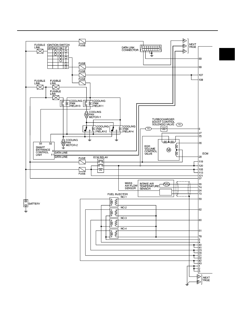
Circuit Diagram
EBS014SX
MBWA0630E
|
|
|
TROUBLE DIAGNOSIS EC-1291 [YD (WITHOUT EURO-OBD)] C D E F G H I J K L M A EC Circuit Diagram EBS014SX MBWA0630E |