Almera Tino V10 (2003 year). Manual - part 70
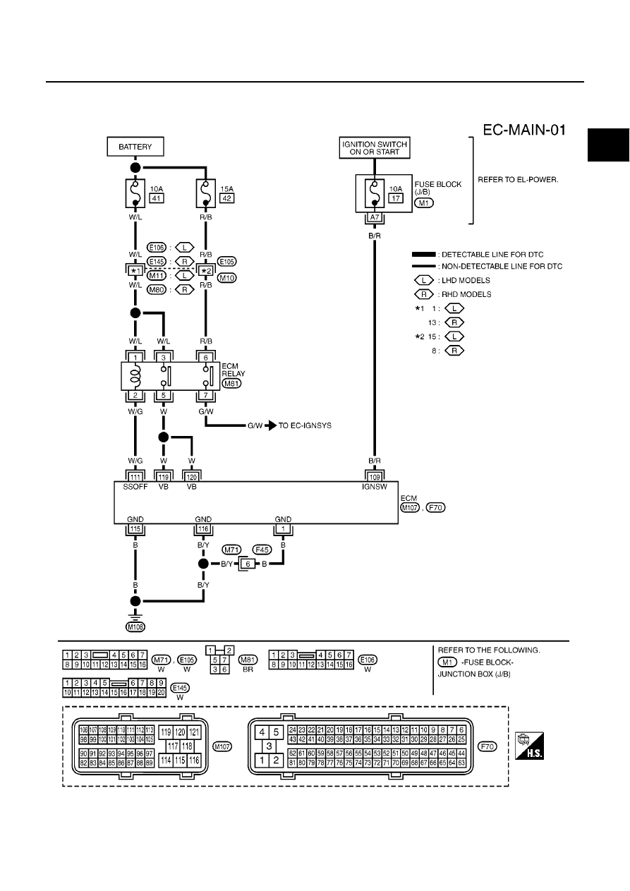
POWER SUPPLY CIRCUIT FOR ECM
EC-139
[QG (WITH EURO-OBD)]
C
D
E
F
G
H
I
J
K
L
M
A
EC
POWER SUPPLY CIRCUIT FOR ECM
PFP:24110
Wiring Diagram
EBS00QHE
YEC432A
|
|
|
POWER SUPPLY CIRCUIT FOR ECM EC-139 [QG (WITH EURO-OBD)] C D E F G H I J K L M A EC POWER SUPPLY CIRCUIT FOR ECM PFP:24110 Wiring Diagram EBS00QHE YEC432A |