Almera Tino V10 (2003 year). Manual - part 53


  Index      Manuals     Almera Tino V10 (2003 year) - Service and Repair Manual


Search            copyright infringement  


Content      ..     51      52      53      54     ..


Almera Tino V10 (2003 year). Manual - part 53


1

CHECK SELF-DIAGNOSTIC RESULTS

Check self-diagnostic results.

MTBL1613

CAUTION:

When on a turntable, such as at a parking structure entrance, or when on a moving object with engine running,
the ESP OFF indicator lamp might turn on and self-diagnosis using the CONSULT-II yaw rate sensor system mal-
function might be displayed, but in this case there is no problem with yaw rate/side G sensor system. As soon as
the vehicle leaves the turntable or moving object, restart engine to return the system to normal.

Is above displayed in self-diagnosis display items?

Yes

©

GO TO 2.

No

©

INSPECTION END

2

CHECK CONNECTOR

1. Disconnect yaw rate/side G sensor connector B66 and ABS actuator and electric unit (control unit) connector E143 and

check terminals for deformation, disconnection, looseness, and so on. If there is an error, repair or replace terminal.

2. Reconnect connectors and perform an ABS actuator and electric unit (control unit) self-diagnosis again.

OK or NG

OK

©

Connector terminal contact is loose, damaged, open or shorted.

NG

©

GO TO 3.

3

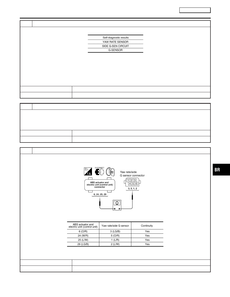
CHECK YAW RATE SENSOR/SIDE G SENSOR HARNESS

1. Turn ignition switch OFF and disconnect yaw rate/side G sensor connector B66 and ABS actuator and electric unit

(control unit) connector E143.

PFIA0460E

2. Check continuity between ABS actuator and electric unit (control unit) connector and yaw rate/side G sensor connector.

MTBL1614

OK or NG

OK

©

GO TO 4.

NG

©

If there is an open or short in harness, repair or replace harness.

GI

MA

EM

LC

EC

FE

CL

MT

AT

AX

SU

ST

RS

BT

HA

SC

EL

IDX

TROUBLE DIAGNOSIS

ESP/TCS/ABS

Inspection 6 Yaw Rate/Side G sensor System (Cont’d)

BR-131

4

CHECK YAW RATE SENSOR/SIDE G SENSOR

1. Connect yaw rate/side G sensor B66 and ABS actuator and electric unit (control unit) connector E143.
2. Use “Data Monitor” to check if yaw rate sensor/side/decel G sensor are normal.

MTBL1615

OK or NG

OK

©

Perform ABS actuator and electric unit (control unit) self-diagnosis again.

NG

©

Replace the malfunctioning yaw rate sensor/side G sensor, and then perform ABS actua-
tor and electric unit (control unit) self-diagnosis again.

Inspection 7 Solenoid and ESP Change-over
Valve System

NLBR0186

INSPECTION PROCEDURE

1

CHECK SELF-DIAGNOSTIC RESULTS

Check self-diagnostic results.

MTBL1616

Is above displayed in self-diagnosis display items?

Yes

©

GO TO 2.

No

©

INSPECTION END

2

CHECK CONNECTOR

1. Disconnect ABS actuator and electric unit (control unit) connector E143 check terminals for deformation, disconnection,

looseness, and so on. If there is an error, repair or replace terminal.

2. Securely reconnect connectors and perform self-diagnosis.

OK or NG

OK

©

Connector terminal contact is loose, damaged, open or shorted.

NG

©

GO TO 3.

TROUBLE DIAGNOSIS

ESP/TCS/ABS

Inspection 6 Yaw Rate/Side G sensor System (Cont’d)

BR-132

3

CHECK SOLENOID POWER AND GROUND CIRCUIT

1. Disconnect ABS actuator and electric unit (control unit) connector E143.
2. Check voltage between ABS actuator and electric unit (control unit) harness connector E143 and ground.

LFIA0148E

MTBL1617

3. Check resistance between ABS actuator and electric unit (control unit) harness connector E143 and ground.

LFIA0152E

MTBL1618

OK or NG

OK

©

Perform self-diagnosis again. If the same results appear, replace ABS actuator and elec-
tric unit (control unit). Refer to BR-151.

NG

©

Repair harness or connectors.

GI

MA

EM

LC

EC

FE

CL

MT

AT

AX

SU

ST

RS

BT

HA

SC

EL

IDX

TROUBLE DIAGNOSIS

ESP/TCS/ABS

Inspection 7 Solenoid and ESP Change-over Valve System (Cont’d)

BR-133

Inspection 8 Actuator Motor, Motor Relay, and
Circuit

=NLBR0187

INSPECTION PROCEDURE

1

CHECK SELF-DIAGNOSTIC RESULTS (1)

Check self-diagnostic results.

MTBL1619

Is above displayed in self-diagnosis display items?

Yes

©

GO TO 2.

No

©

INSPECTION END

2

CHECK SELF-DIAGNOSTIC RESULTS (2)

1. Disconnect ABS actuator and electric unit (control unit) connector E143. Then reconnect it securely.
2. Perform self-diagnosis again.

Do any self-diagnosis items appear?

Yes

©

GO TO 3.

No

©

Repair or replace the applicable connector.

TROUBLE DIAGNOSIS

ESP/TCS/ABS

Inspection 8 Actuator Motor, Motor Relay, and Circuit

BR-134

3

CHECK ABS MOTOR AND MOTOR RELAY POWER SYSTEM

1. Disconnect ABS actuator and electric unit (control unit) connector E143.
2. Check voltage between ABS actuator and electric unit (control unit) connector E143 and ground.

LFIA0149E

MTBL1620

3. Check resistance between ABS actuator and electric unit (control unit) connector E143 and ground.

LFIA0147E

MTBL1621

OK or NG

OK

©

Perform self-diagnosis again. If the same result appears, replace ABS actuator and elec-
tric unit (control unit). Refer to BR-151.

NG

©

Repair harness or connectors.

GI

MA

EM

LC

EC

FE

CL

MT

AT

AX

SU

ST

RS

BT

HA

SC

EL

IDX

TROUBLE DIAGNOSIS

ESP/TCS/ABS

Inspection 8 Actuator Motor, Motor Relay, and Circuit (Cont’d)

BR-135

Inspection 9 ABS Actuator and Electric Unit
(Control Unit) Power Supply and Ground
Circuit

=NLBR0188

INSPECTION PROCEDURE

1

CHECK SELF-DIAGNOSTIC RESULTS

Check self-diagnostic results.

MTBL1622

Does “BATTERY VOLTAGE” appear in self-diagnostic results display?

Yes

©

GO TO 2.

No

©

INSPECTION END

2

CHECK STARTING

1. Disconnect ABS actuator and electric unit (control unit) connector E143. Then reconnect it securely.
2. Perform self-diagnosis.

Do any self-diagnosis items appear?

Yes

©

GO TO 3.

No

©

Repair or replace connector.

3

CHECK ABS ACTUATOR AND ELECTRIC UNIT (CONTROL UNIT) POWER SUPPLY

1. Disconnect ABS actuator and electric unit (control unit) connector E143.
2. Turn ignition switch ON (but do not start engine). Check voltage between ABS actuator and electric unit (control unit)

harness connector E143 and ground.

LFIA0151E

MTBL1623

OK or NG

OK

©

GO TO 4.

NG

©

GO TO 5.

TROUBLE DIAGNOSIS

ESP/TCS/ABS

Inspection 9 ABS Actuator and Electric Unit (Control Unit) Power Supply and Ground Circuit

BR-136

4

CHECK ABS ACTUATOR AND ELECTRIC UNIT (CONTROL UNIT) GROUND CIRCUITS

Check ABS actuator and electric unit (control unit) ground circuits.

LFIA0152E

MTBL1624

OK or NG

OK

©

Perform ABS actuator and electric unit (control unit) self-diagnosis again.

NG

©

Repair harness or connectors.

5

CHECK ABS ACTUATOR AND ELECTRIC UNIT (CONTROL UNIT) POWER SYSTEM

1. Disconnect ABS actuator and electric unit (control unit) connector E143.
2. Check continuity between battery positive terminal and ABS actuator and electric unit (control unit) connector E143.

PFIA0461E

MTBL1625

OK or NG

Yes

©

Check for malfunction conditions in battery (terminal looseness, low voltage, etc.) and
alternator.

No

©

Repair harness or connectors.

GI

MA

EM

LC

EC

FE

CL

MT

AT

AX

SU

ST

RS

BT

HA

SC

EL

IDX

TROUBLE DIAGNOSIS

ESP/TCS/ABS

Inspection 9 ABS Actuator and Electric Unit (Control Unit) Power Supply and Ground Circuit (Cont’d)

BR-137

Inspection 10 Stop Lamp Switch System

NLBR0189

INSPECTION PROCEDURE

1

CHECK SELF-DIAGNOSTIC RESULTS

Check self-diagnostic results.

MTBL1626

Is above displayed in self-diagnosis display items?

Yes

©

GO TO 2.

No

©

INSPECTION END

2

CHECK CONNECTOR

1. Disconnect the stop lamp switch connector F30 (QG engine), F12 (YD22DDT engine), F66 (YD22DDTi engine) and

ABS actuator and electric unit (control unit) connector E143 and check terminals for deformation, disconnection,
looseness, and so on. If any malfunction is found, repair or replace terminal.

2. Securely reconnect connectors.
3. Start engine.
4. Repeat pumping brake pedal carefully several times, then perform self-diagnosis again.

OK or NG

OK

©

Connector terminal contact is loose, damaged, open or shorted.

NG

©

GO TO 3.

3

CHECK STOP LAMP SWITCH CIRCUIT

1. Turn ignition switch OFF and disconnect stop lamp switch connector F30 (QG engine), F12 (model with YD22DDT

engine), F66 (YD22DDTi engine) and ABS actuator and electric unit (control unit) connector E143.

YBR374

2. Check continuity between stop lamp switch harness connector F30 (QG engine), F12 (model with YD22DDT engine),

F66 (YD22DDTi engine) and ABS actuator and electric unit (control unit) harness connector E143.

MTBL1627

OK or NG

OK

©

Connect connectors and perform an ABS actuator and electric unit (control unit) self-di-
agnosis.

NG

©

Open or short in harness. Repair or replace harness.

TROUBLE DIAGNOSIS

ESP/TCS/ABS

Inspection 10 Stop Lamp Switch System

BR-138

Inspection 11 Brake Fluid Level Sensor System

=NLBR0190

INSPECTION PROCEDURE

1

CHECK SELF-DIAGNOSTIC RESULTS

1. Check the brake reservoir tank fluid level. If the level is low, add brake fluid.
2. Erase self-diagnostic results and check self-diagnostic results.

MTBL1628

Is above displayed in self-diagnosis display items?

Yes

©

GO TO 2.

No

©

INSPECTION END

2

CHECK CONNECTOR

1. Disconnect the brake fluid level sensor connector E86 and ABS actuator and electric unit (control unit) connector E143

and check terminal for deformation, disconnection, looseness, and so on. If there is any malfunction condition, repair or
replace terminal.

2. Securely reconnect connectors and perform self-diagnosis again.

OK or NG

OK

©

Connector terminal contact is loose, damaged, open or shorted.

NG

©

GO TO 3.

3

CHECK HARNESS BETWEEN THE BRAKE FLUID LEVEL SENSOR AND ABS ACTUATOR AND ELEC-
TRIC UNIT (CONTROL UNIT)

1. Turn ignition switch OFF and disconnect the brake fluid level sensor connector E86, ABS actuator and electric unit

(control unit) connectors E143.

YBR375

2. Check continuity between the brake fluid level sensor connector E86 and ABS actuator and electric unit (control unit)

connector E143 and ground.

MTBL1629

OK or NG

OK

©

Connect connectors and perform an ABS actuator and electric unit (control unit) self-di-
agnosis.

NG

©

If there is an open or short in harness, repair or replace harness.

GI

MA

EM

LC

EC

FE

CL

MT

AT

AX

SU

ST

RS

BT

HA

SC

EL

IDX

TROUBLE DIAGNOSIS

ESP/TCS/ABS

Inspection 11 Brake Fluid Level Sensor System

BR-139

Inspection 12 When “ST ANG SEN SIGNAL”
Appears on Self-diagnostic Results Display

=NLBR0191

INSPECTION PROCEDURE

1

CHECK SELF-DIAGNOSTIC RESULTS (1)

Check self-diagnostic results.

MTBL1630

Does anything besides “ST ANG SEN SIGNAL” appear on self-diagnostic results display?

Yes

©

Inspect and repair the indicated items. Then perform self-diagnosis again.

No

©

Adjust steering angle sensor neutral position. Then GO TO 2.

2

CHECK SELF-DIAGNOSTIC RESULTS (2)

Turin ignition switch OFF, and ON to erase self-diagnostic results, and perform ABS actuator and electric unit (control unit)
self-diagnosis again.

Does anything appear on self-diagnostic results display?

Yes

©

Replace steering angle sensor. Then adjust neutral position and perform self-diagnosis
again.

No

©

INSPECTION END

Inspection 13 CAN Communication System

NLBR0192

INSPECTION PROCEDURE

1

CHECK SELF-DIAGNOSTIC RESULTS (1)

Check self-diagnostic results.

MTBL1631

Do self-diagnostic results indicate anything other than above?

Yes

©

Repair or replace the item indicated.

No

©

GO TO 2.

TROUBLE DIAGNOSIS

ESP/TCS/ABS

Inspection 12 When “ST ANG SEN SIGNAL” Appears on Self-diagnostic Results Display

BR-140

2

CHECK CONNECTORS AND HARNESS BETWEEN ABS ACTUATOR AND ELECTRIC UNIT (CONTROL
UNIT) AND STEERING ANGLE SENSOR

1. Turn ignition switch OFF. Disconnect battery ground cable.
2. Disconnect ABS actuator and electric unit (control unit) connector E143 and steering angle sensor connector E129.
3. Check for open circuit and short circuits in harness between ABS actuator and electric unit (control unit) harness con-

nector E143 and steering angle sensor harness connector E129.

4. Check all control unit and sensor connectors, (Check for missing, bent, or collapsed terminals in terminal housing.)

OK or NG

OK

©

GO TO 3.

NG

©

Harness connector malfunction. Repair or replace. GO TO 3.

3

CHECK SELF-DIAGNOSTIC RESULTS (2)

1. Connect connectors to all control units and sensors.
2. Connect battery ground cable. Turn ignition switch ON.
3. Erase self-diagnostic results. Then start engine and perform self-diagnosis.

Does only “STEERING ANGLE SENSOR COMMUNICATION SYSTEM” appear on self-diagnostic results display?

Yes

©

Replace spiral cable (steering angle sensor) and adjust steering angle sensor neutral
position. Refer to BR-82.

No

©

GO TO 4.

4

CAN COMMUNICATION SYSTEM CHECK

Check the data monitor item “CAN DIAG SUPPORT MNTR”.

MTBL1632

©

After printing out the monitor item, go to CAN system. Refer to EL-5.

GI

MA

EM

LC

EC

FE

CL

MT

AT

AX

SU

ST

RS

BT

HA

SC

EL

IDX

TROUBLE DIAGNOSIS

ESP/TCS/ABS

Inspection 13 CAN Communication System (Cont’d)

BR-141

Inspection 14 When “ESTM VEH SPD SIG”
Appears on Self-diagnostic Results Display

=NLBR0194

INSPECTION PROCEDURE

1

CHECK SELF-DIAGNOSTIC RESULTS

Conduct an A/T self-diagnostic results.

MTBL1634

Does anything besides “ESTM VEH SPD SIG” appear on self-diagnostic results display?

Yes

©

Check and repair the indicated items. Then perform self-diagnosis again.

No

©

I

Erase A/T self-diagnosis. INSPECTION END.
NOTE:
If there is no error about ABS actuator and electric unit (control unit), “ESTM VHE
SPD SIG” may be displayed in A/T self-diagnosis depending on the timing of cranking.

Inspection 15 ESP OFF Indicator Lamp Does
Not Illuminate.

NLBR0195

INSPECTION PROCEDURE

1

CHECK ESP OFF INDICATOR LAMP

Disconnect ABS actuator and electric unit (control unit) connector E143.

Do ABS warning lamp and ESP OFF indicator lamp illuminate?

OK

©

Malfunction in combination meter system. Inspect combination meter.

NG

©

Malfunction of ABS actuator and electric unit (control unit). Repair or replace control unit.

YBR376

Component Inspection

NLBR0196

ESP OFF SWITCH

NLBR0196S01

I

Turn ignition switch OFF, and disconnect the ESP OFF switch
connector E121, and check continuity between terminals 1 and
2.

1 - 2:

Continuity should exist when pushing the switch.
Continuity should not exist when releasing the
switch.

TROUBLE DIAGNOSIS

ESP/TCS/ABS

Inspection 14 When “ESTM VEH SPD SIG” Appears on Self-diagnostic Results Display

BR-142

Symptom 1 Excessive ABS Function Operation
Frequency

NLBR0197

1

CHECK WHEEL SENSOR

Check the following:

I

Sensor mount and damage

I

Sensor rotor mount and damage

I

Sensor connector connection

I

Sensor harness

OK or NG

OK

©

GO TO 2.

NG

©

Replace sensor or sensor rotor.

2

CHECK FRONT AND REAR AXLE

Make sure there is no excessive play in front and rear axles.

OK or NG

OK

©

GO TO 3.

NG

©

Repair.

3

CHECK ABS WARNING LAMP DISPLAY

Make sure ABS warning lamp turns OFF approximately 2 sec. after ignition switch is turned on or when driving.

OK or NG

OK

©

Normal

NG

©

Perform self-diagnosis. Refer to BR-112.

Symptom 2 Unexpected Pedal Reaction

NLBR0198

1

CHECK BRAKE PEDAL STROKE

Check brake pedal stroke.

Is the stroke too long?

Yes

©

I

Bleed air from the brake piping.

I

Check the brake pedal, brake booster, and master cylinder mount for play, looseness,
and brake system for fluid leaks, etc. If any malfunctions are found, make repair.

No

©

GO TO 2.

2

CHECK PEDAL FORCE

Make sure that brake is effective with pedal depressed.

Is pedal heavy, but affective?

Yes

©

Normal

No

©

GO TO 3.

GI

MA

EM

LC

EC

FE

CL

MT

AT

AX

SU

ST

RS

BT

HA

SC

EL

IDX

TROUBLE DIAGNOSIS

ESP/TCS/ABS

Symptom 1 Excessive ABS Function Operation Frequency

BR-143

3

CHECK FUNCTION

Disconnect ABS actuator and electric unit (control unit) connector E143 and make sure the braking force is sufficient when
ABS is not operating. After the inspection, reconnect connector.

OK or NG

Yes

©

GO TO 4.

No

©

Check brake system.

4

CHECK ABS WARNING LAMP DISPLAY

Make sure ABS warning lamp turns OFF approximately 2 sec. after ignition switch is turned ON or when driving.

OK or NG

Yes

©

Normal

No

©

GO TO 5.

5

CHECK WHEEL SENSOR

Check the following:

I

Sensor mount and damage

I

Sensor rotor mount and damage

I

Sensor connector connection

I

Sensor harness

OK or NG

Yes

©

Normal

No

©

Replace sensor or sensor rotor.

Symptom 3 The Braking Distance Is Long

NLBR0199

CAUTION:

On slippery road surfaces, the stopping distance might be
longer with ABS operating than when ABS is not operating.

1

CHECK FUNCTION

Disconnect ABS actuator and electric unit (control unit) connector E143 to deactivate ABS. In this condition, check stop-
ping distance. After inspection, connect connector.

Is stopping distance still long?

Yes

©

I

Bleed air from the brake piping.

I

Check brake system.

No

©

GO TO 2.

2

CHECK ABS WARNING LAMP DISPLAY

Make sure ABS warning lamp turns OFF approximately 2 sec. after ignition switch is turned ON or when driving.

OK or NG

Yes

©

Normal

No

©

GO TO 3.

TROUBLE DIAGNOSIS

ESP/TCS/ABS

Symptom 2 Unexpected Pedal Reaction (Cont’d)

BR-144

3

CHECK WHEEL SENSOR

Check the following:

I

Sensor mount and damage

I

Sensor rotor mount and damage

I

Sensor connector connection

I

Sensor harness

OK or NG

Yes

©

Normal

No

©

Replace sensor or sensor rotor.

Symptom 4 ABS Function Does Not Operate

NLBR0200

CAUTION:

ABS does not operate when vehicle speed is 10 km/h (6 MPH)
or less.

1

CHECK ABS WARNING LAMP DISPLAY

Make sure ABS warning lamp turns OFF approximately 2 second after ignition switch is turned on or when driving.

OK or NG

OK

©

GO TO 2.

NG

©

Perform self-diagnosis. Refer to BR-112.

2

CHECK WHEEL SENSOR

Check the following:

I

Sensor mount and damage

I

Sensor rotor mount and damage

I

Sensor connector connection

I

Sensor harness

OK or NG

OK

©

Normal

NG

©

Replace sensor or sensor rotor.

Symptom 5 Pedal Vibration or ABS Operation
Sound Occurs

NLBR0201

CAUTION:

Under the following conditions, when brake pedal is lightly
depressed (just place a foot on it), ABS is activated and vibra-
tion is felt. However, this is normal.

I

When shifting gears

I

When driving on slippery road

I

During cornering at high speed

I

When passing over bumps or grooves

I

When pulling away just after starting engine [at approxi-
mately 10 km/h (6 MPH) or higher]

1

SYMPTOM CHECK 1

Check if pedal vibration or operation sound occurs when engine is started.

OK or NG

OK

©

Perform self-diagnosis. Refer to BR-112.

NG

©

GO TO 2.

GI

MA

EM

LC

EC

FE

CL

MT

AT

AX

SU

ST

RS

BT

HA

SC

EL

IDX

TROUBLE DIAGNOSIS

ESP/TCS/ABS

Symptom 3 The Braking Distance Is Long (Cont’d)

BR-145

2

INSPECTION (1)

Does vibration occur during normal parking?

CAUTION:

In addition to activation for sudden braking, ABS may activate in conditions such as those listed below.

I

Roads with low surface

I

Turning at high speed

I

Passing through gusts of wind

OK or NG

OK

©

GO TO 3.

NG

©

Normal

3

INSPECTION (2)

Check for vibration when engine speed is increased while vehicle is stopped.

OK or NG

OK

©

GO TO 4.

NG

©

I

Normal

CAUTION:

Vibration may occur when vehicle is stopped.

4

INSPECTION (3)

Check for vibration when switches of electrical components are operated.

OK or NG

OK

©

Check for any wireless devices, or antenna lead near control unit (including wiring).

NG

©

GO TO 5.

5

CHECKING ABS WARNING LAMP INDICATION

Make sure that ABS warning lamp turns on.

OK or NG

OK

©

Perform self-diagnosis. Refer to BR-112.

NG

©

GO TO 6.

6

CHECK WHEEL SENSORS

Check the following:

I

Sensor mounting

I

Sensor pick-up for iron chips

I

Sensor connector engagement

I

Wheel sensor circuit

OK or NG

OK

©

Normal

NG

©

Repair wheel sensor and sensor rotor system.

TROUBLE DIAGNOSIS

ESP/TCS/ABS

Symptom 5 Pedal Vibration or ABS Operation Sound Occurs (Cont’d)

BR-146


Content      ..     51      52      53      54     ..