Almera Tino V10 (2003 year). Manual - part 54
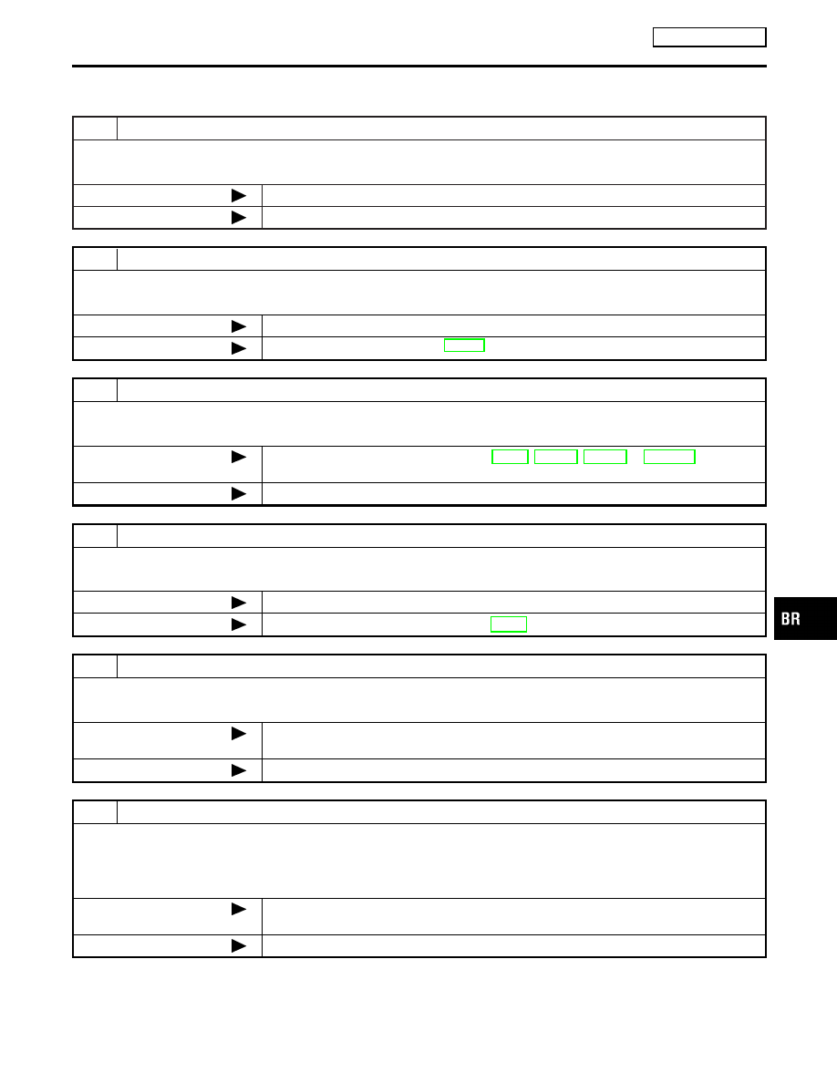
Symptom 6 Vehicle Jerks During ESP/TCS/ABS
Control
NLBR0202
1
CHECK ENGINE SPEED SIGNAL
Conduct CONSULT-II ABS actuator and electric unit (control unit) “Data Monitor”.
Is engine speed at idle 400 rpm or higher?
Yes
Normal.
No
GO TO 2.
2
CHECK ABS WARNING LAMP DISPLAY
Make sure ABS warning lamp turns OFF approximately 2 sec. after ignition switch is turned on or when driving.
OK or NG
OK
GO TO 3.
NG
Perform self-diagnosis. Refer to BR-112.
3
CHECK ECM SELF-DIAGNOSTIC RESULTS
Perform ECM self-diagnosis.
Are self-diagnosis items displayed?
Yes
Check the corresponding items. Refer to EC-20, EC-554, EC-938 or EC-1252 in “Engine
Control (EC section)”.
No
GO TO 4.
4
CHECK A/T SELF-DIAGNOSTIC RESULTS
Perform A/T self-diagnosis.
OK or NG
OK
GO TO 6.
NG
Check the corresponding items. Refer to AT-35.
5
SELF-DIAGNOSTIC RESULTS INSPECTION 1
Perform self-diagnosis of ABS actuator and electric unit (control unit).
Are self-diagnosis items displayed?
Yes
Check the corresponding items, make repairs, and perform ABS actuator and electric
unit (control unit) self-diagnosis again.
No
GO TO 7.
6
CHECK CONNECTOR
1. Disconnect ABS actuator and electric unit (control unit) E143 and the ECM connector, check terminals for deformation,
disconnection, looseness, and so on. If there is an error, repair or replace connector.
2. Securely reconnect connector and perform self-diagnosis.
OK or NG
OK
If connector terminal contact is loose, damaged, open or shorted, repair or replace con-
nector terminal.
NG
GO TO 7.
GI
MA
EM
LC
EC
FE
CL
MT
AT
AX
SU
ST
RS
BT
HA
SC
EL
IDX
TROUBLE DIAGNOSIS
ESP/TCS/ABS
Symptom 6 Vehicle Jerks During ESP/TCS/ABS Control
BR-147