Almera Tino V10 (2003 year). Manual - part 22
TROUBLE DIAGNOSES FOR SYMPTOMS
AT-337
[EXC.F/EURO-OBD]
D
E
F
G
H
I
J
K
L
M
A
B
AT
20. Vehicle Does Not Decelerate By Engine Brake
ECS009AQ
SYMPTOM:
Vehicle does not decelerate by engine brake when shifting from 2
2
(1
2
) to 1
1
.
1.
CHECK SYMPTOM
Is 6. Vehicle Does Not Creep Backward In “R” Position OK?
Yes or No
Yes
>> Go to
AT-332, "15. Engine Speed Does Not Return To Idle (Light Braking D
.
No
>> Go to
AT-317, "6. Vehicle Does Not Creep Backward In “R” Position"
.
21. TCM Self-diagnosis Does Not Activate (PNP & Overdrive Control Switches,
and Throttle Position Sensor Circuit Checks)
ECS009AR
SYMPTOM:
O/D OFF indicator lamp does not come on in TCM self-diagnostic procedure even if the lamp circuit is
good.
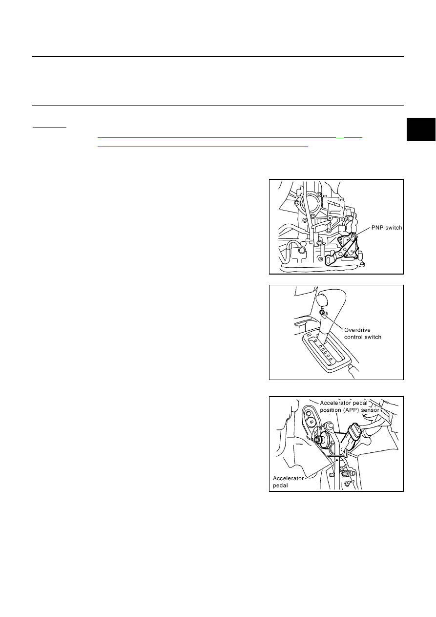
DESCRIPTION
●
PNP switch
The PNP switch assembly includes a transmission position switch. The transmission position switch
detects the selector lever position and sends a signal to the TCM.
●
Overdrive control switch
SCIA0752E
MCIA0103E
MCIA0096E