Almera Tino V10 (2003 year). Manual - part 17
TROUBLE DIAGNOSIS — INTRODUCTION
AT-257
[EXC.F/EURO-OBD]
D
E
F
G
H
I
J
K
L
M
A
B
AT
TROUBLE DIAGNOSIS — INTRODUCTION
PFP:00000
Introduction
ECS0099W
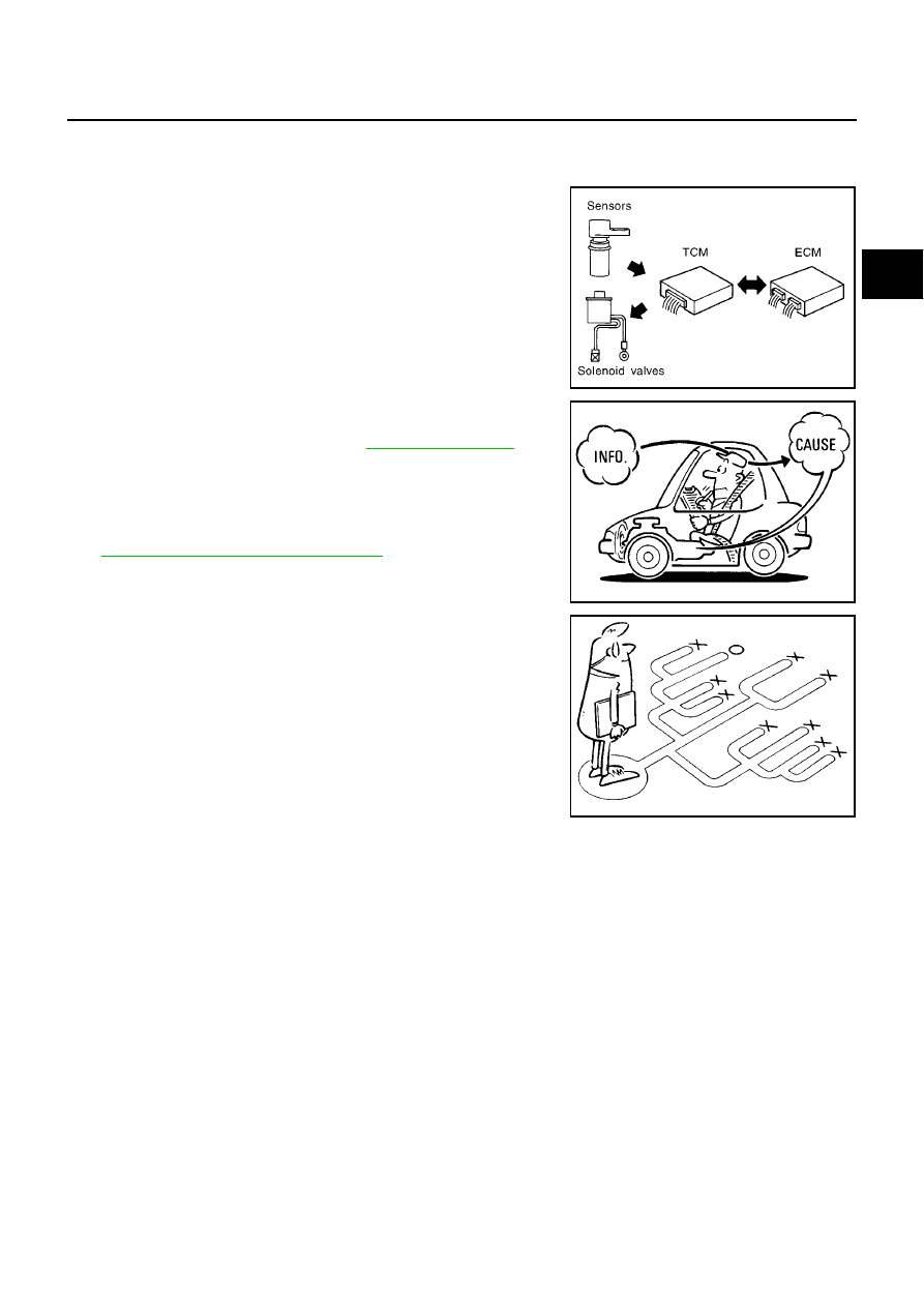
The TCM receives a signal from the vehicle speed sensor, throttle
position sensor or PNP switch and provides shift control or lock-up
control via A/T solenoid valves.
Input and output signals must always be correct and stable in the
operation of the A/T system. The A/T system must be in good oper-
ating condition and be free of valve seizure, solenoid valve malfunc-
tion, etc.
It is much more difficult to diagnose a problem that occurs intermit-
tently rather than continuously. Most intermittent problems are
caused by poor electric connections or improper wiring. In this case,
careful checking of suspected circuits may help prevent the replace-
ment of good parts.
A visual check only, may not find the cause of the problems. A road
test with CONSULT-II or a circuit tester connected should be per-
formed. Follow the “Work Flow”. Refer to
.
Before undertaking actual checks, take a few minutes to talk with a
customer who approaches with a drive ability complaint. The cus-
tomer can supply good information about such problems, especially
intermittent ones. Find out what symptoms are present and under
what conditions they occur. A “Diagnostic Worksheet” like the exam-
ple (
AT-258, "DIAGNOSTIC WORKSHEET"
) should be used.
Start your diagnosis by looking for “conventional” problems first. This
will help troubleshoot drive ability problems on an electronically con-
trolled engine vehicle.
Also check related Service bulletins for information.
SAT631IA
SAT632I
SEF234G