Almera Tino V10 (2003 year). Manual - part 11


  Index      Manuals     Almera Tino V10 (2003 year) - Service and Repair Manual


Search            copyright infringement  


Content      ..     9      10      11      12     ..


Almera Tino V10 (2003 year). Manual - part 11


DTC P0740 TORQUE CONVERTER CLUTCH SOLENOID VALVE

AT-161

[EURO-OBD]

D

E

F

G

H

I

J

K

L

M

A

B

AT

DTC P0740 TORQUE CONVERTER CLUTCH SOLENOID VALVE

PFP:31940

Description

ECS00985

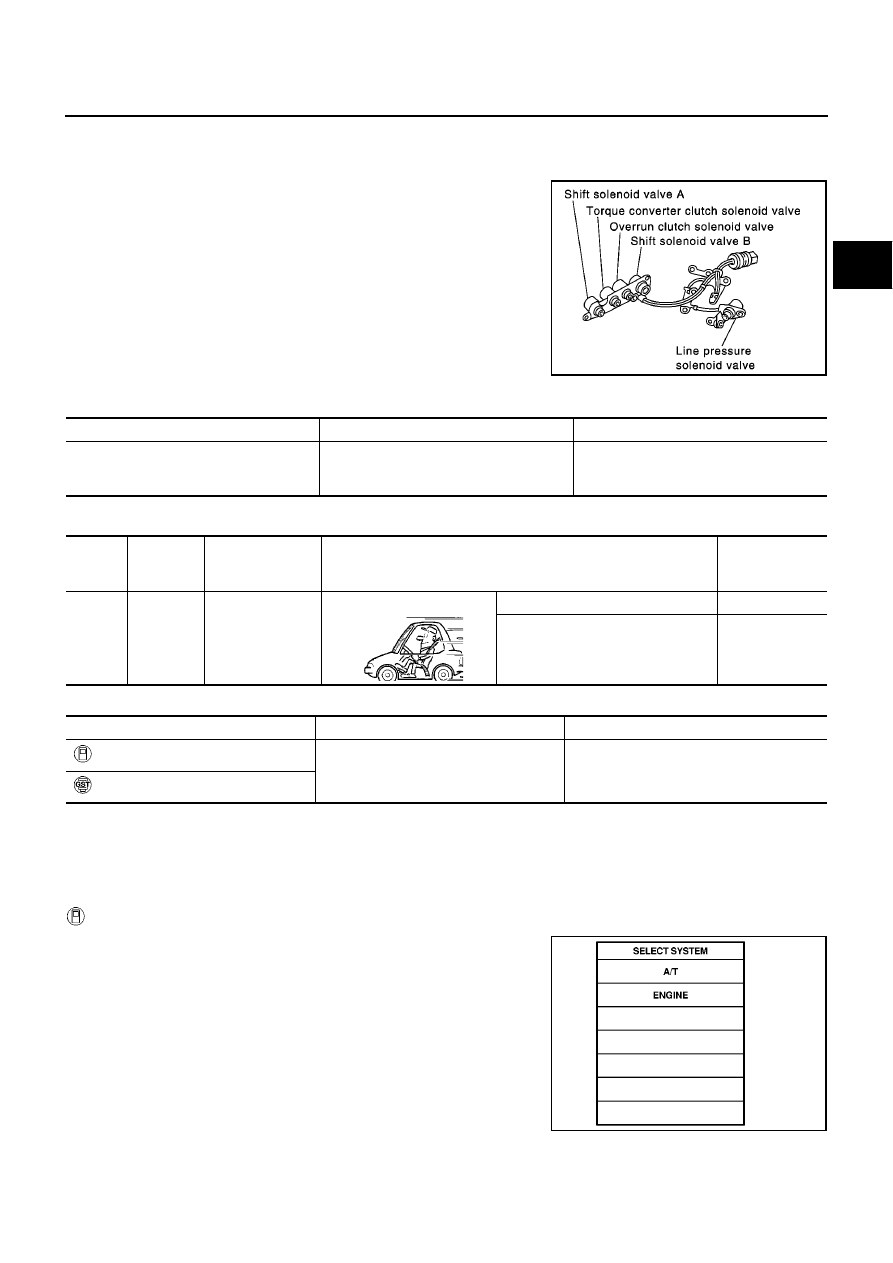
The torque converter clutch solenoid valve is activated, with the gear
in “D

4

”, by the TCM in response to signals sent from the vehicle

speed and throttle position sensors. Lock-up piston operation will
then be controlled.
Lock-up operation, however, is prohibited when A/T fluid tempera-
ture is too low.
When the accelerator pedal is depressed (less than 2/8) in lock-up
condition, the engine speed should not change abruptly. If there is a
big jump in engine speed, there is no lock-up.

CONSULT-II REFERENCE VALUE IN DATA MONITOR MODE

Remarks: Specification data are reference values.

TCM TERMINALS AND REFERENCE VALUE

Remarks: Specification data are reference values.

ON BOARD DIAGNOSIS LOGIC

DIAGNOSTIC TROUBLE CODE (DTC) CONFIRMATION PROCEDURE

NOTE:
If “DIAGNOSTIC TROUBLE CODE CONFIRMATION PROCEDURE” has been previously conducted,
always turn ignition switch “OFF” and wait at least 5 seconds before conducting the next test.
After the repair, perform the following procedure to confirm the malfunction is eliminated.

With CONSULT-II

1.

Turn ignition switch “ON”.

2.

Select “DATA MONITOR” mode for “ENGINE” with CONSULT-II
and wait at least 1 second.

SCIA0718E

Monitor item

Condition

Specification

Torque converter clutch solenoid valve
duty

Lock-up “OFF”

Lock-up “ON”

Approximately 4%

Approximately 94%

Termi-

nal No.

Wire color

Item

Condition

Judgement stan-

dard

(Approx.)

3

GY/R

Torque converter
clutch solenoid
valve

When A/T performs lock-up.

8 - 15V

When A/T does not perform lock-up.

0V

Diagnostic trouble code

Malfunction is detected when...

Check items (Possible cause)

: TCC SOLENOID/CIRC

TCM detects an improper voltage drop
when it tries to operate the solenoid valve.

Harness or connectors
(The solenoid circuit is open or shorted.)

T/C clutch solenoid valve

: P0740

SAT014K

AT-162

[EURO-OBD]

DTC P0740 TORQUE CONVERTER CLUTCH SOLENOID VALVE

3.

If DTC is detected, go to

AT-164, "Diagnostic Procedure"

.

With GST

Follow the procedure “With CONSULT-II”.

SAT020K

DTC P0740 TORQUE CONVERTER CLUTCH SOLENOID VALVE

AT-163

[EURO-OBD]

D

E

F

G

H

I

J

K

L

M

A

B

AT

Wiring Diagram — AT — TCV

ECS00986

YAT377A

AT-164

[EURO-OBD]

DTC P0740 TORQUE CONVERTER CLUTCH SOLENOID VALVE

Diagnostic Procedure

ECS00987

1.

CHECK VALVE RESISTANCE

1.

Turn ignition switch to “OFF” position.

2.

Disconnect terminal cord assembly connector in engine compartment.

3.

Check resistance between terminal 5 and ground.

OK or NG

OK

>> GO TO 2

NG

>> 1. Remove oil pan. Refer to

AT-410, "ON-VEHICLE

SERVICE"

.

2. Check the following items:

Torque converter clutch solenoid valve
Refer to

AT-164, "Component Inspection"

.

Harness of terminal cord assembly for short or open

2.

CHECK POWER SOURCE CIRCUIT

1.

Turn ignition switch to “OFF” position.

2.

Disconnect TCM harness connector.

3.

Check continuity between terminal 5 and TCM harness connector terminal 3.

If OK, check harness for short to ground and short to power.

4.

Reinstall any part removed.

OK or NG

OK

>> GO TO 3

NG

>> Repair open circuit or short to ground or short to power

in harness or connectors.

3.

CHECK DTC

Perform

AT-161, "DIAGNOSTIC TROUBLE CODE (DTC) CONFIRMATION PROCEDURE"

.

OK or NG

OK

>> INSPECTION END

NG

>> 1. Perform TCM input/output signal inspection.

2. If NG, recheck TCM pin terminals for damage or loose connection with harness connector.

Component Inspection

ECS00988

TORQUE CONVERTER CLUTCH SOLENOID VALVE

For removal, refer to

AT-410, "Control Valve Assembly and Accumulators"

.

Resistance: 5 - 20

MCIA0081E

Continuity should exist.

MCIA0082E

DTC P0740 TORQUE CONVERTER CLUTCH SOLENOID VALVE

AT-165

[EURO-OBD]

D

E

F

G

H

I

J

K

L

M

A

B

AT

Resistance Check

Check resistance between two terminals.

Operation Check

Check solenoid valve by listening for its operating sound while
applying battery voltage to the terminal and ground.

Solenoid valve

Terminal No.

Resistance

(Approx.)

Torque converter
clutch solenoid
valve

5

Ground

5 - 20

MCIA0083E

MCIA0084E

AT-166

[EURO-OBD]

DTC P0745 LINE PRESSURE SOLENOID VALVE

DTC P0745 LINE PRESSURE SOLENOID VALVE

PFP:31940

Description

ECS00989

The line pressure solenoid valve regulates the oil pump discharge
pressure to suit the driving condition in response to a signal sent
from the TCM.

NOTE:
The line pressure duty cycle value is not consistent when the
closed throttle position switch is “ON”. To confirm the line
pressure duty cycle at low pressure, the accelerator (throttle)
should be open until the closed throttle position switch is
“OFF”.

CONSULT-II REFERENCE VALUE IN DATA MONITOR MODE

Remarks: Specification data are reference values.

NOTE:
The line pressure duty cycle value is not consistent when the closed throttle position switch is “ON”. To confirm the line pressure duty
cycle at low pressure, the accelerator (throttle) should be open until the closed throttle position switch is “OFF”.

TCM TERMINALS AND REFERENCE VALUE

Remarks: Specification data are reference values.

ON BOARD DIAGNOSIS LOGIC

SCIA0735E

Monitor item

Condition

Specification

Line pressure solenoid valve duty

Small throttle opening

(Low line pressure)

Large throttle opening

(High line pressure)

Approximately 24%

Approximately 95%

Termi-

nal No.

Wire color

Item

Condition

Judgement stan-

dard

(Approx.)

1

R/W

Line pressure
solenoid valve

When releasing accelerator pedal
after warming up engine.

1.5 - 3.0V

When depressing accelerator pedal
fully after warming up engine.

0V

2

P/B

Line pressure
solenoid valve
(with dropping
resistor)

When releasing accelerator pedal
after warming up engine.

4 - 14V

When depressing accelerator pedal
fully after warming up engine.

0V

Diagnostic trouble code

Malfunction is detected when...

Check items (Possible cause)

: L/PRESS SOL/CIRC

TCM detects an improper voltage drop
when it tries to operate the solenoid valve.

Harness or connectors
(The solenoid circuit is open or shorted.)

Line pressure solenoid valve

: P0745

DTC P0745 LINE PRESSURE SOLENOID VALVE

AT-167

[EURO-OBD]

D

E

F

G

H

I

J

K

L

M

A

B

AT

DIAGNOSTIC TROUBLE CODE (DTC) CONFIRMATION PROCEDURE

NOTE:
If “DIAGNOSTIC TROUBLE CODE CONFIRMATION PROCEDURE” has been previously conducted,
always turn ignition switch “OFF” and wait at least 5 seconds before conducting the next test.
After the repair, perform the following procedure to confirm the malfunction is eliminated.

With CONSULT-II

1.

Turn ignition switch “ON” and select “DATA MONITOR” mode for
“ENGINE” with CONSULT-II.

2.

Depress accelerator pedal completely and wait at least 1 sec-
ond.

3.

If DTC is detected, go to

AT-169, "Diagnostic Procedure"

.

With GST

Follow the procedure “With CONSULT-II”.

SAT014K

SAT020K

AT-168

[EURO-OBD]

DTC P0745 LINE PRESSURE SOLENOID VALVE

Wiring Diagram — AT — LPSV

ECS0098A

YAT378A

DTC P0745 LINE PRESSURE SOLENOID VALVE

AT-169

[EURO-OBD]

D

E

F

G

H

I

J

K

L

M

A

B

AT

Diagnostic Procedure

ECS0098B

1.

CHECK VALVE RESISTANCE

1.

Turn ignition switch to “OFF” position.

2.

Disconnect terminal cord assembly connector in engine compartment.

3.

Check resistance between terminal 4 and ground.

OK or NG

OK

>> GO TO 2

NG

>> 1. Remove control valve assembly. Refer to

AT-410,

"Control Valve Assembly and Accumulators"

.

2. Check the following items:

Line pressure solenoid valve
Refer to

AT-171, "Component Inspection"

.

Harness of terminal cord assembly for short or open

2.

CHECK POWER SOURCE CIRCUIT

1.

Turn ignition switch to “OFF” position.

2.

Disconnect TCM harness connector.

3.

Check resistance between terminal 4 and TCM harness connector terminal 2.

OK or NG

OK

>> GO TO 3

NG

>> Check the following items:

Dropping resistor
Refer to

AT-171, "Component Inspection"

.

Harness for short or open between TCM terminal 2
and terminal cord assembly (Main harness)

Resistance: 2.5 - 5

MCIA0085E

Resistance: 10 - 15

MCIA0086E

AT-170

[EURO-OBD]

DTC P0745 LINE PRESSURE SOLENOID VALVE

3.

CHECK POWER SOURCE CIRCUIT

1.

Turn ignition switch to “OFF” position.

2.

Check resistance between terminal 4 and TCM harness connector terminal 1.

If NG, check harness for short to ground and short to power.

3.

Reinstall any part removed.

OK or NG

OK

>> GO TO 4

NG

>> Repair open circuit or short to ground or short to power

in harness or connectors.

4.

CHECK DTC

Perform

AT-167, "DIAGNOSTIC TROUBLE CODE (DTC) CONFIRMATION PROCEDURE"

.

OK or NG

OK

>> INSPECTION END

NG

>> 1. Perform TCM input/output signal inspection.

2. If NG, recheck TCM pin terminals for damage or loose connection with harness connector.

Resistance: Approx. 0

MCIA0087E

DTC P0745 LINE PRESSURE SOLENOID VALVE

AT-171

[EURO-OBD]

D

E

F

G

H

I

J

K

L

M

A

B

AT

Component Inspection

ECS0098C

LINE PRESSURE SOLENOID VALVE

For removal, refer to

AT-410, "Control Valve Assembly and Accumulators"

.

Resistance Check

Check resistance between two terminals.

Operation Check

Check solenoid valve by listening for its operating sound while
applying battery voltage to the terminal and ground.

Solenoid valve

Terminal No.

Resistance

(Approx.)

Line pressure
solenoid valve

4

Ground

2.5 - 5

MCIA0088E

MCIA0089E

AT-172

[EURO-OBD]

DTC P0745 LINE PRESSURE SOLENOID VALVE

DROPPING RESISTOR

Check resistance between two terminals.

Resistance: 10 - 15

MCIA0090E

DTC P0750 SHIFT SOLENOID VALVE A

AT-173

[EURO-OBD]

D

E

F

G

H

I

J

K

L

M

A

B

AT

DTC P0750 SHIFT SOLENOID VALVE A

PFP:31940

Description

ECS0098D

Shift solenoid valves A and B are turned “ON” or “OFF” by the TCM
in response to signals sent from the PNP switch, vehicle speed and
throttle position sensors. Gears will then be shifted to the optimum
position.

TCM TERMINALS AND REFERENCE VALUE

Remarks: Specification data are reference values.

ON BOARD DIAGNOSIS LOGIC

SCIA0718E

Gear position

1

2

3

4

Shift solenoid valve A

ON (Closed)

OFF (Open)

OFF (Open)

ON (Closed)

Shift solenoid valve B

ON (Closed)

ON (Closed)

OFF (Open)

OFF (Open)

Termi-

nal No.

Wire color

Item

Condition

Judgement stan-

dard

(Approx.)

11

L/W

Shift solenoid
valve A

When shift solenoid valve A oper-
ates.
(When driving in “D

1

” or “D

4

”.)

Battery voltage

When shift solenoid valve A does not
operate.
(When driving in “D

2

” or “D

3

”.)

0V

Diagnostic trouble code

Malfunction is detected when...

Check items (Possible cause)

: SFT SOL A/CIRC

TCM detects an improper voltage drop
when it tries to operate the solenoid valve.

Harness or connectors
(The solenoid circuit is open or shorted.)

Shift solenoid valve A

: P0750

AT-174

[EURO-OBD]

DTC P0750 SHIFT SOLENOID VALVE A

DIAGNOSTIC TROUBLE CODE (DTC) CONFIRMATION PROCEDURE

CAUTION:

Always drive vehicle at a safe speed.
NOTE:
If “DIAGNOSTIC TROUBLE CODE CONFIRMATION PROCEDURE” has been previously conducted,
always turn ignition switch “OFF” and wait at least 5 seconds before conducting the next test.
After the repair, perform the following procedure to confirm the malfunction is eliminated.

With CONSULT-II

1.

Turn ignition switch “ON” and select “DATA MONITOR” mode for
“ENGINE” with CONSULT-II.

2.

Start engine.

3.

Drive vehicle in D position and allow the transmission to shift “1”

“2” (“GEAR”).

4.

If DTC is detected, go to

AT-176, "Diagnostic Procedure"

.

With GST

Follow the procedure “With CONSULT-II”.

SAT014K

SAT020K

DTC P0750 SHIFT SOLENOID VALVE A

AT-175

[EURO-OBD]

D

E

F

G

H

I

J

K

L

M

A

B

AT

Wiring Diagram — AT — SSV/A

ECS0098E

YAT379A

AT-176

[EURO-OBD]

DTC P0750 SHIFT SOLENOID VALVE A

Diagnostic Procedure

ECS0098F

1.

CHECK VALVE RESISTANCE

1.

Turn ignition switch to “OFF” position.

2.

Disconnect terminal cord assembly connector in engine compartment.

3.

Check resistance between terminal 2 and ground.

OK or NG

OK

>> GO TO 2

NG

>> 1. Remove control valve assembly. Refer to

AT-410,

"Control Valve Assembly and Accumulators"

.

2. Check the following items:

Shift solenoid valve A
Refer to

AT-177, "Component Inspection"

.

Harness of terminal cord assembly for short or open

2.

CHECK POWER SOURCE CIRCUIT

1.

Turn ignition switch to “OFF” position.

2.

Disconnect TCM harness connector.

3.

Check continuity between terminal 2 and TCM harness connector terminal 11.

If OK, check harness for short to ground and short to power.

4.

Reinstall any part removed.

OK or NG

OK

>> GO TO 3

NG

>> Repair open circuit or short to ground or short to power

in harness or connectors.

3.

CHECK DTC

Perform

AT-174, "DIAGNOSTIC TROUBLE CODE (DTC) CONFIRMATION PROCEDURE"

.

OK or NG

OK

>> INSPECTION END

NG

>> 1. Perform TCM input/output signal inspection.

2. If NG, recheck TCM pin terminals for damage or loose connection with harness connector.

Resistance: 20 - 30

MCIA0091E

Continuity should exist.

MCIA0092E


Content      ..     9      10      11      12     ..