Almera Tino V10 (2003 year). Manual - part 10
DTC P0732 A/T 2ND GEAR FUNCTION
AT-145
[EURO-OBD]
D
E
F
G
H
I
J
K
L
M
A
B
AT
Diagnostic Procedure
ECS0097V
1.
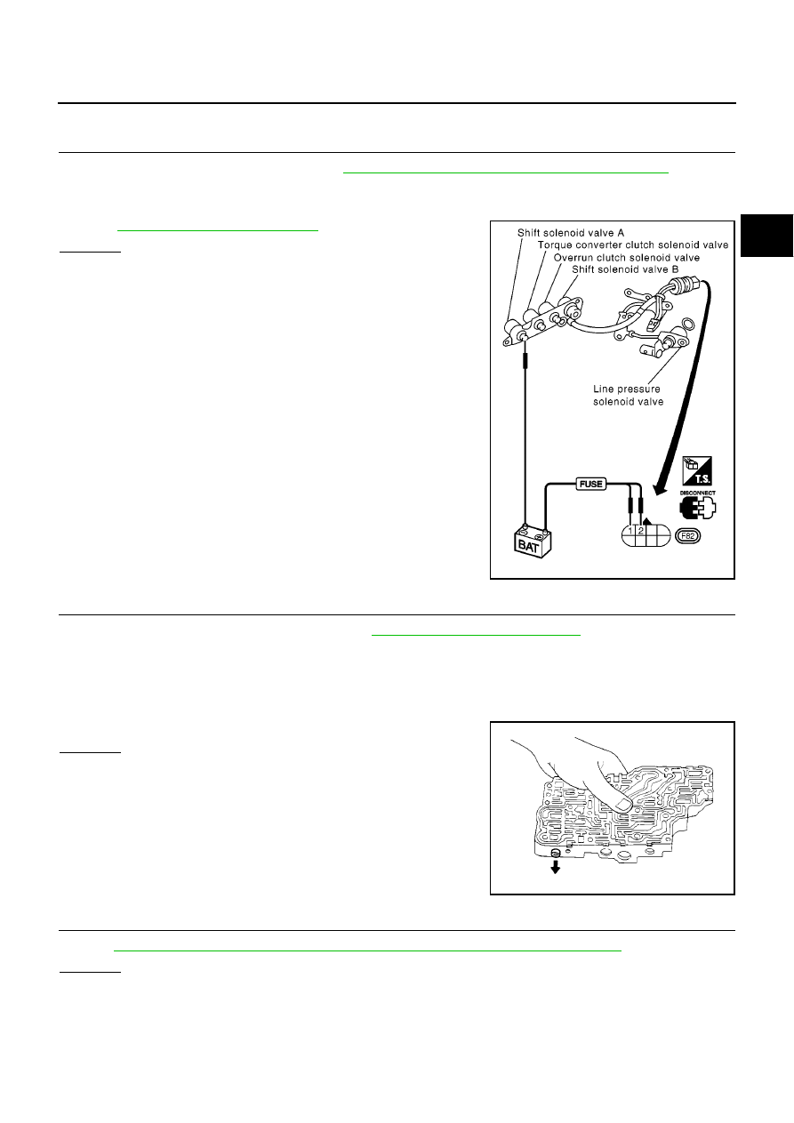
CHECK SHIFT SOLENOID VALVE
1.
Remove control valve assembly. Refer to
AT-410, "Control Valve Assembly and Accumulators"
.
2.
Check shift solenoid valve operation.
●
Shift solenoid valve B
Refer to
AT-146, "Component Inspection"
.
OK or NG
OK
>> GO TO 2
NG
>> Repair or replace shift solenoid valve assembly.
2.
CHECK CONTROL VALVE
1.
Disassemble control valve assembly. Refer to
AT-443, "Control Valve Assembly"
.
2.
Check to ensure that:
●
Valve, sleeve and plug slide along valve bore under their own weight.
●
Valve, sleeve and plug are free from burrs, dents and scratches.
●
Control valve springs are free from damage, deformation and fatigue.
●
Hydraulic line is free from obstacles.
OK or NG
OK
>> GO TO 3
NG
>> Repair control valve assembly.
3.
CHECK DTC
Perform
AT-142, "DIAGNOSTIC TROUBLE CODE (DTC) CONFIRMATION PROCEDURE"
.
OK or NG
OK
>> INSPECTION END
NG
>> Check control valve again. Repair or replace control valve assembly.
MCIA0070E
SAT367H