Nissan Almera Tino V10. Manual - part 953
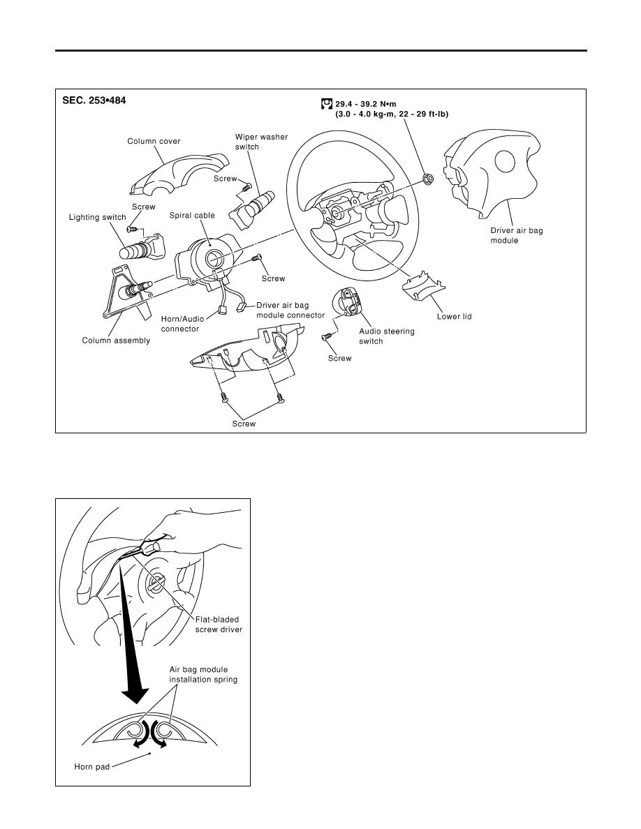
Driver Air Bag Module and Spiral Cable
REMOVAL AND INSTALLATION
NLRS0015
YRS107
MHIA0017E
REMOVAL
NLRS0016
CAUTION:
I
Before servicing SRS, turn the ignition switch off, discon-
nect both battery cables and wait at least 3 minutes.
I
Always work from the side of driver air bag module.
1.
Push the top of horn pad downward.
2.
Rotate the air bag module installation spring to inner direction
with a flat-bladed screwdriver, remove air bag module.
3.
Disconnect the air bag harness connector. Then remove driver
air bag module.
CAUTION:
When removal of driver air bag module connector, insert the
lock using flat-bladed driver with cloth. Then push up the lock.
4.
Disconnect the horn connector.
SUPPLEMENTAL RESTRAINT SYSTEM (SRS)
Driver Air Bag Module and Spiral Cable
RS-24