Nissan Almera Tino V10. Manual - part 952
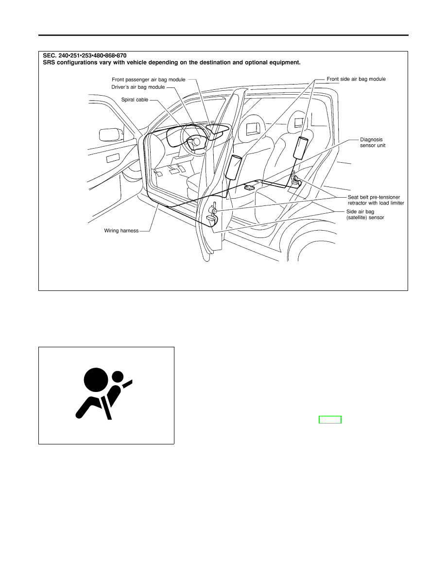
SRS Component Parts Location
NLRS0011
NRS102
SRS797-A
Maintenance Items
NLRS0012
CAUTION:
Do not use electrical test equipment to check SRS circuit.
1.
Check operation of “AIR BAG” warning lamp.
After turning ignition key to “ON” position, “AIR BAG” warning
lamp illuminates. The “AIR BAG” warning lamp will go off after
about 7 seconds if no malfunction is detected. If any of the fol-
lowing “AIR BAG” warning lamp conditions occur, immediately
check the air bag system. Refer to RS-43 for details.
I
The “AIR BAG” warning lamp does not illuminate when the
ignition switch is turned “ON”.
I
The “AIR BAG” warning lamp does not go off about 7 seconds
after the ignition switch is turned “ON”.
I
The “AIR BAG” warning lamp blinks after about 7 seconds after
the ignition switch is turned “ON”.
2.
Visually check SRS components.
1)
Diagnosis sensor unit
I
Check diagnosis sensor unit and bracket for dents, cracks and
deformities.
I
Check connectors for damage, and terminals for deformities.
2)
Air bag module and steering wheel
I
Remove air bag module from steering wheel, instrument panel
SUPPLEMENTAL RESTRAINT SYSTEM (SRS)
SRS Component Parts Location
RS-20