Nissan Almera Tino V10. Manual - part 872


  Index      Nissan     Nissan Almera Tino V10 - Service Manual (2003 year)


Search            


Content   ..  870  871  872  873   ..


Nissan Almera Tino V10. Manual - part 872


EM-144

[YD]

VACUUM PUMP

14. Remove camshaft position sensor.

15. Remove cylinder head rear cover plate.

16. Loosen and remove the installation bolts in rear cam sprocket.

Loosen rear cam sprocket installation bolts by fixing the hexagonal portion of the camshaft.

17. Remove vacuum pump and cylinder head rear cover assembly.

Remove and install vacuum pump, sprocket, drive chain and
chain guide as an assembly.

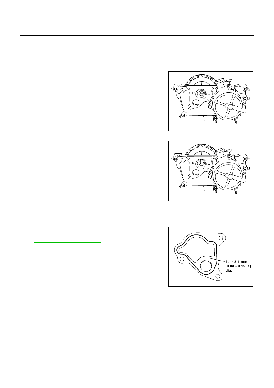
Loosen mounting bolts in reverse order shown in figure.

Do not remove any bolts not shown in figure. (Especially
never remove M6 bolts on vacuum pump.)

Use seal cutter (special service tool) or other suitable tool to
remove.

INSTALLATION

1.

Install vacuum pump and cylinder head rear cover assembly
onto cylinder head. Refer to

EM-143, "Removal and Installation"

.

Camshaft sprocket and camshaft need mating angle when
installing to cylinder head.

Apply Genuine Liquid Gasket or equivalent (Refer to

EM-110,

"Precautions for Liquid Gasket"

.) to area shown in the figure.

Attaching should be done with in 5 minutes after coating.

2.

Tighten mounting bolts in order shown in the figure.

3.

Install rear cam sprocket mounting bolts by fixing the hexagonal
portion of the camshaft.

4.

Tighten rear cam sprocket mounting bolts.

Check if the chain tension is excessive.

5.

Install cylinder head rear cover plate.

Apply Genuine Liquid Gasket or equivalent (Refer to

EM-110,

"Precautions for Liquid Gasket"

.) to area shown in the figure.

Attaching should be done with in 5 minutes after coating.

CAUTION:

Never start engine with vacuum circuit being open. If
engine is started and vehicle is running while vacuum
pump is open (with vacuum hose disconnected), PCV flow
rate will increase and engine may be damaged.

6.

Install in reverse order of removal after this step.

When vacuum hose is connected, insert it securely by at least
15 mm (0.59 in).

INSPECTION AFTER INSTALLATION

Check generated vacuum satisfies the specification at idle speed. Refer to

EM-143, "INSPECTION BEFORE

REMOVAL"

.

SBIA0167E

SBIA0167E

SBIA0169E

VACUUM PUMP

EM-145

[YD]

C

D

E

F

G

H

I

J

K

L

M

A

EM

Disassembly and Assembly

EBS00QFL

DISASSEMBLY

1.

Push on chain guide lightly so that clearance between chain and chain guide part reaches 0 mm (0 in).
Then loosen chain guide mounting bolts.

2.

Remove chain from rear cam sprocket and vacuum pump sprocket.

3.

Remove rear cam sprocket.

4.

Remove vacuum pump.

CAUTION:

Do not disassemble vacuum pump.

ASSEMBLY

Follow procedure below to install each part onto cylinder head rear
cover.

1.

Install vacuum pump.

2.

Temporarily fit chain guide.

MBIA0033E

1.

Rear cam sprocket

2.

Drive chain

3.

Chain guide

4.

Cylinder head rear cover

5.

Vacuum pump

SBIA0171E

EM-146

[YD]

VACUUM PUMP

3.

Install rear cam sprocket.

Sprocket can be installed in any direction.

4.

Fit drive chain onto rear cam sprocket and vacuum pump
sprocket.

5.

Push on chain guide lightly so that clearance between chain and
chain guide sliding part reaches 0 mm (0 in). Then tighten chain
guide mounting bolts.

SBIA0172E

INJECTION TUBE AND FUEL INJECTOR

EM-147

[YD]

C

D

E

F

G

H

I

J

K

L

M

A

EM

INJECTION TUBE AND FUEL INJECTOR

PFP:00018

Removal and Installation

EBS00QFM

CAUTION:

Apply new engine oil to parts marked in illustration before installation.

REMOVAL

1.

Remove engine cover. Refer to

EM-160, "Removal and Installation"

.

2.

Remove harness connector from fuel injector.

3.

Remove spill hose.

4.

Following steps below, remove injection tubes.

a.

Put a paint mark or tag on injection tubes to identify each cylin-
der.

Use a fuel-resistant method.

b.

Remove injection tubes in order of 2-1-4-3 individually.

CAUTION:

Be careful not to allow leaked fuel to contaminate engine
compartment. Especially, ensure to keep engine mount
insulator clear of fuel.
NOTE:
Removal procedure of fuel injector is shown right.

MBIA0011E

1.

Spill tube

2.

Eye-bolt

3.

Spill tube gasket

4.

Nozzle support

5.

Fuel injector

6.

O-ring

7.

Nozzle gasket

8.

Nozzle oil seal

9.

Injection tube No. 1

10.

Injection tube No. 2

11.

Injection tube No. 3

12.

Injection tube No. 4

13.

Injection tube center

14.

Fuel rail assembly

SBIA0203E


Content   ..  870  871  872  873   ..