Nissan Almera Tino V10. Manual - part 843


  Index      Nissan     Nissan Almera Tino V10 - Service Manual (2003 year)


Search            


Content   ..  841  842  843  844   ..


Nissan Almera Tino V10. Manual - part 843


EM-28

[QG]

SPARK PLUG (CONVENTIONAL)

SPARK PLUG (CONVENTIONAL)

PFP:22401

Removal and Installation

EBS00QEE

REMOVAL

1.

Disconnect ignition coil harness connector from ignition coil.

2.

Remove ignition coil.

3.

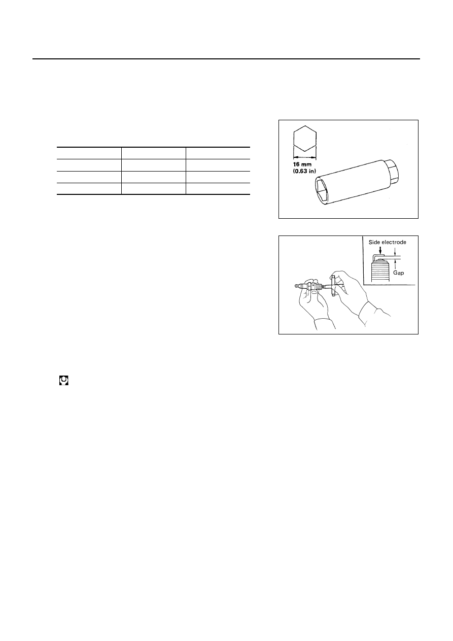
Remove spark plugs with a spark plug wrench (commercial ser-
vice tool).

Spark plug

INSPECTION AFTER REMOVAL

Check spark plug gap. Adjust or replace if necessary.

Use a wire brush for cleaning, if necessary.

INSTALLATION

Install in the reverse order of removal, paying attention to the following.

Make

NGK

Champion

Standard type

LFR5A-11

REC10YC4

Hot type

LFR4A-11

Cold type

LFR6A-11

SMA581C

Standard

: 1.0 - 1.1 mm (0.039 - 0.043 in)

SMA476

Spark plug:

: 19.6 - 29.4 N·m (2.0 - 3.0 kg-m, 15 - 21 ft-lb)

FUEL INJECTOR AND FUEL TUBE

EM-29

[QG]

C

D

E

F

G

H

I

J

K

L

M

A

EM

FUEL INJECTOR AND FUEL TUBE

PFP:16600

Removal and Installation

EBS00QEF

CAUTION:

Apply new engine oil when installing the parts that specified to do so in the figure.

Do not remove or disassembly parts unless instructed as shown in the figure.

REMOVAL

1.

Release fuel pressure. Refer to

EC-52, "FUEL PRESSURE RELEASE"

(WITH EURO-OBD),

EC-579,

"FUEL PRESSURE RELEASE"

(WITHOUT EURO-OBD).

2.

Disconnect harness for fuel injector, and move it aside.

3.

Remove fuel hose.

CAUTION:

After removal, install blind plug to fuel hose to prevent the fuel from draining.

4.

Remove fuel tube and injector assembly with the following pro-
cedure:

a.

Loosen mounting bolts in reverse order shown in figure.

b.

Pull out fuel injector/fuel tube assembly toward engine rear side.

MBIA0039E

1.

Fuel tube

2.

Fuel feed hose

3.

O-ring

4.

Clip

5.

Fuel injector

6.

Intake manifold

PBIC0617E

EM-30

[QG]

FUEL INJECTOR AND FUEL TUBE

CAUTION:

Do not touch fuel injector nozzle with intake manifold or other parts.

5.

Remove fuel injector from fuel tube.

Release clip and remove it.

Pull fuel injector straight out of fuel tube.

CAUTION:

Be careful not to damage nozzle part.

Avoid any impact such as a dropping.

Do not disassemble or adjust it.

INSTALLATION

1.

When installing O-ring to fuel injector, follow instructions described below.

CAUTION:

Handle O-ring with bare hands. Never wear gloves.

Lubricate O-ring with new engine oil.

Do not clean O-ring with solvent.

Make sure that O-ring and its mating part are free of foreign material.

Be careful not to scratch it with a tool or fingernails during installation. Also be careful not to
twist or stretch O-ring. If O-ring is stretched while being attached, do not insert it into fuel tube
immediately.

Insert O-ring straight into fuel tube. Do not angle or twist it.

2.

Install fuel injector to fuel tube with the following procedure.

a.

Insert clip into clip mounting groove on fuel injector.

Insert clip so that lug “A” of fuel injector matches notch “A” of
the clip.

CAUTION:

Do not reuse clip. Replace it with a new one.

Be careful to keep clip from interfering with O-ring. If
interference occurs, replace O-ring.

b.

Insert fuel injector into fuel tube with clip attached.

Insert it while matching it to the axial center.

Insert fuel injector so that lug “B” of fuel tube matches notch
“B” of the clip.

Make sure that fuel tube flange is securely fixed in flange fix-
ing groove on clip.

c.

Make sure that installation is complete by checking that fuel
injector does not rotate or come off.

PBIC0620E

PBIC1021E

FUEL INJECTOR AND FUEL TUBE

EM-31

[QG]

C

D

E

F

G

H

I

J

K

L

M

A

EM

3.

Tighten mounting bolts in two steps in numerical order shown in
figure.

4.

Install fuel feed hose.

CAUTION:

Install hose clamp avoiding interference with bulge, and
securely tighten it

5.

Install remaining parts in the reverse order of removal.

INSPECTION AFTER INSTALLATION

Check for fuel leakage with following procedure.

1.

Turn ignition switch ON (do not start engine), and check connections for leakage by applying fuel pressure
to fuel piping.

2.

Start engine, and re-check connections for fuel leakage by increasing engine speed.

1st step : 11.8 - 13.7 N·m (1.2 - 1.4 kg-m, 9 - 10 ft-lb)

2nd step : 16.7 - 23.5 N·m (1.7 - 2.4 kg-m, 12 - 17 ft-lb)

PBIC0617E


Content   ..  841  842  843  844   ..