Nissan Almera Tino V10. Manual - part 796
3
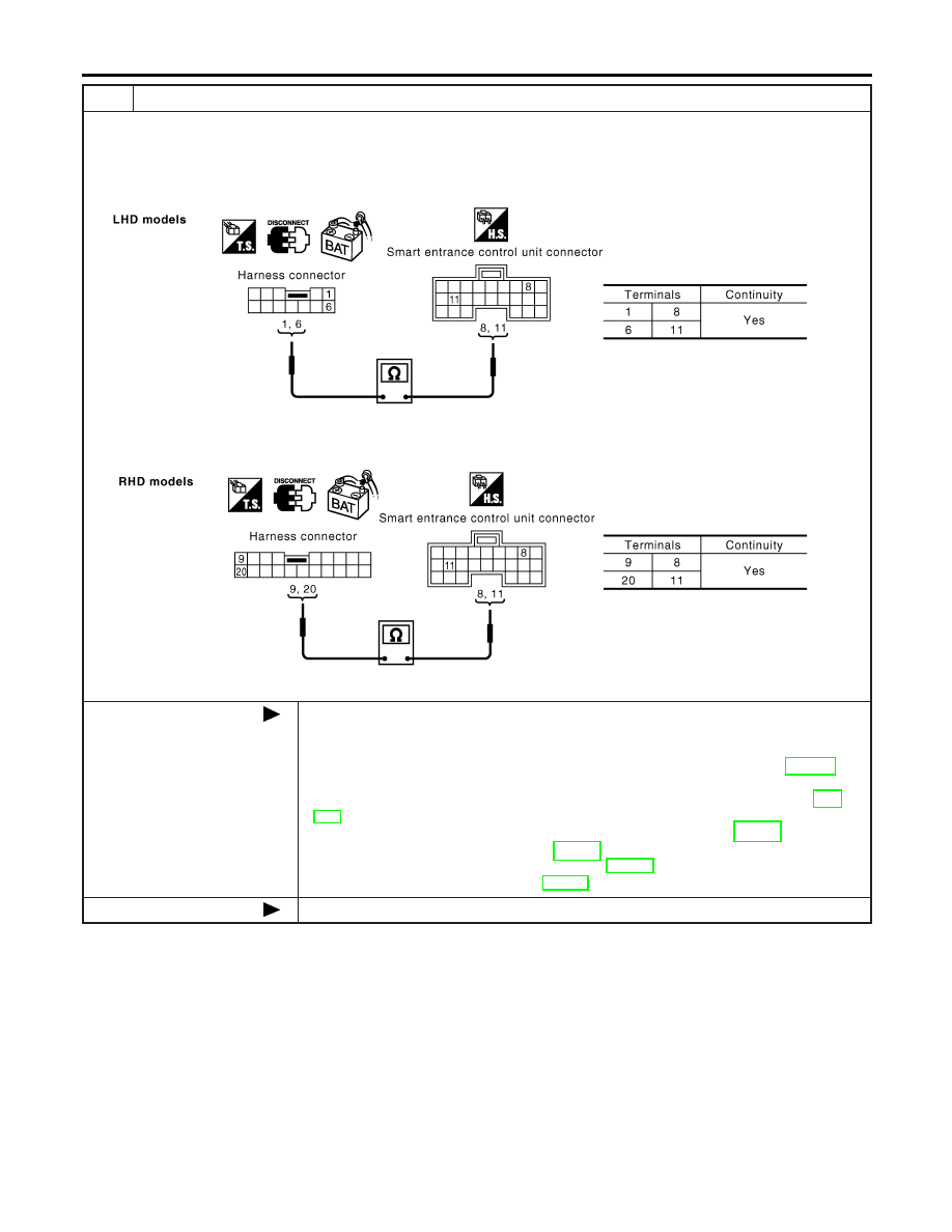
CHECK HARNESS FOR OPEN CIRCUIT
1. Disconnect smart entrance control unit connector.
2. Check the following.
LHD models
‰
Continuity between harness connector M82 terminals 1 (L), 6 (R) and smart entrance control unit connector M99 termi-
nals 8 (L), 11 (R)
YEL420E
RHD models
‰
Continuity between harness connector M80 terminals 9 (L), 20 (R) and smart entrance control unit connector M99 termi-
nals 8 (L), 11 (R)
YEL421E
OK or NG
OK
Reconnect all connectors to perform “SELF-DIAG RESULTS” and “DATA MONITOR” for
“ENGINE”, “A/T”, “ABS” and “SMART ENTRANCE” displayed on CONSULT-II. Refer to
the following.
‰
“DTC U1000, U1001 CAN COMMUNICATION LINE” (WITH EURO-OBD) (EC-145) for
“ENGINE”
‰
“DTC U1000, U1001 CAN COMMUNICATION LINE” (WITHOUT EURO-OBD) (EC-
651) for “ENGINE”
‰
“DTC U1000 CAN COMMUNICATION LINE” (WITH EURO-OBD) (AT-194) for “A/T”
‰
“CAN COMMUNICATION LINE” (All) (AT-399) for “A/T”
‰
“Inspection 13 CAN Communication System” (BR-140) for “ABS”
‰
“CAN Communication Line Check” (EL-351) for “SMART ENTRANCE”
NG
Repair harness.
CAN SYSTEM (TYPE 1)
Trouble Diagnoses (Cont’d)
EL-480