Nissan Almera Tino V10. Manual - part 792
TYPE 4
=NLEL0691S03
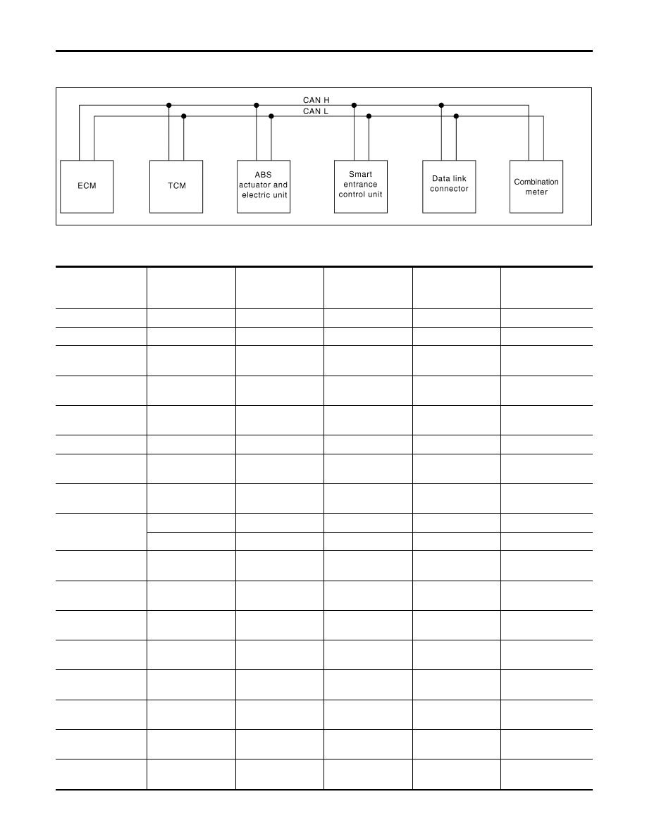
System Diagram
NLEL0691S0301
YEL468E
Input/Output Signal Chart
NLEL0691S0302
T: Transmit R: Receive
Signals
ECM
TCM
ABS actuator and
electric unit (control
unit)
Smart entrance
control unit
Combination meter
Engine speed signal
T
R
Brake switch signal
R
T
Rear window defog-
ger signal
R
T
Heater fan switch
signal
R
T
Air conditioner
switch signal
R
T
MI signal
T
R
Engine coolant tem-
perature signal
T
R
Fuel consumption
signal
T
R
Vehicle speed sig-
nal
T
R
R
T
Seat belt reminder
signal
R
T
Headlamp switch
signal
T
R
Flashing indicator
signal
T
R
Engine cooling fan
speed signal
T
R
Door switches state
signal
T
R
A/C compressor
signal
T
R
A/C compressor
feedback signal
T
R
Accelerator pedal
position signal
T
R
CAN COMMUNICATION
CAN Communication Unit (Cont’d)
EL-464