Nissan Almera Tino V10. Manual - part 769
4
PERFORM INITIALIZATION WITH CONSULT-II AGAIN
1. Replace IMMU (Smart entrance control unit).
2. Perform initialization with CONSULT-II.
For initialization, refer to “CONSULT-II operation manual NATS”.
SEL297W
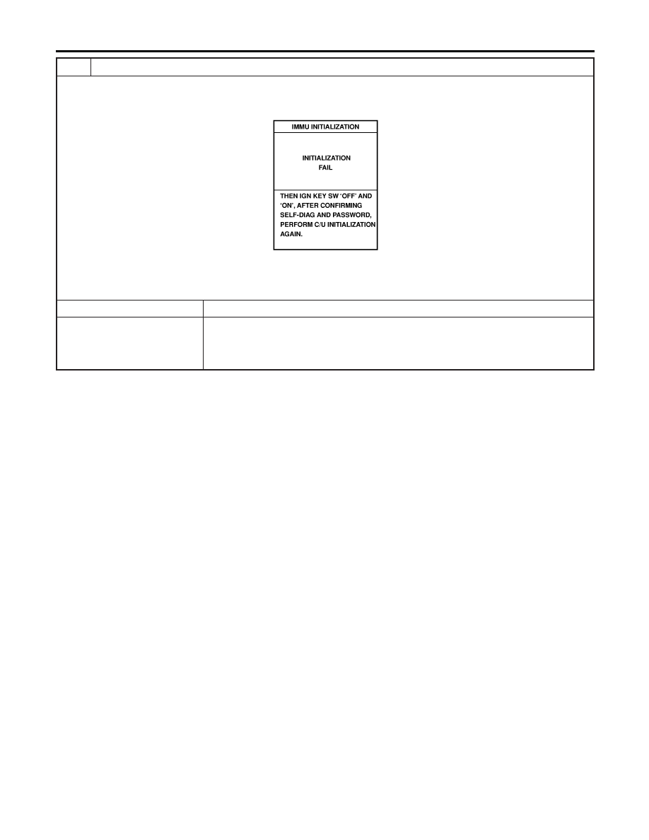
NOTE:
If the initialization is not completed or fails, CONSULT-II shows the above message on the screen.
Can the system be initialized?
Yes
©
System is OK. (IMMU is malfunctioning. Ref. part No. A)
No
©
I
ECM is malfunctioning.
Replace ECM. Ref. part No. B
Perform initialization with CONSULT-II.
For initialization, refer to “CONSULT-II operation manual NATS”.
NATS (NISSAN ANTI-THEFT SYSTEM)
Trouble Diagnoses (Cont’d)
EL-372