Nissan Almera Tino V10. Manual - part 752


  Index      Nissan     Nissan Almera Tino V10 - Service Manual (2003 year)


Search            


Content   ..  750  751  752  753   ..


Nissan Almera Tino V10. Manual - part 752


DOOR LOCK/UNLOCK SWITCH CHECK

NLEL0573S07

1

CHECK DOOR LOCK/UNLOCK SWITCH SIGNAL
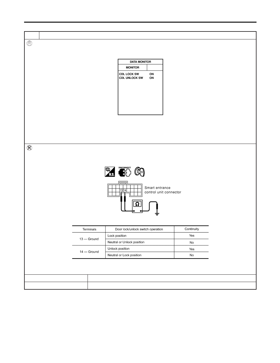
With CONSULT-II

I

Check door lock/unlock switch input signal (“CDL LOCK SW” “CDL UNLOCK SW”) in “DATA MONITOR” mode with
CONSULT-II.

SIIA1566E

When door lock/unlock switch is turned to LOCK:

CDL LOCK SW

ON

When door lock/unlock switch is turned to UNLOCK:

CDL UNLOCK SW

ON

Without CONSULT-II

1. Disconnect smart entrance control unit harness connector.
2. Check continuity between smart entrance control unit harness connector M99 terminal 13 (GY), 14 (L) and ground.

SIIA1567E

MTBL1482

OK or NG

OK

©

Door lock/unlock switch is OK.

NG

©

GO TO 2.

POWER DOOR LOCK — SUPER LOCK —

Trouble Diagnosis (Cont’d)

EL-304

2

CHECK DOOR LOCK/UNLOCK SWITCH

1. Disconnect power window main switch connector.
2. Check continuity between power window main switch terminals.

YEL349E

OK or NG

OK

©

Check the following.

I

Ground circuit for power window main switch

I

Harness for open or short between power window main switch and smart entrance
control unit connector

NG

©

Replace power window main switch (door lock/unlock switch).

GI

MA

EM

LC

EC

FE

CL

MT

AT

AX

SU

BR

ST

RS

BT

HA

SC

IDX

POWER DOOR LOCK — SUPER LOCK —

Trouble Diagnosis (Cont’d)

EL-305

DOOR LOCK ACTUATOR CHECK

=NLEL0573S08

Driver Side

NLEL0573S0801

1

CHECK DOOR LOCK SIGNAL

1. Disconnect door lock actuator (driver side) harness connector.
2. Check voltage between door lock actuator harness connector D10 terminal 3 (L), 6 (W/R) and ground.

YEL354E

MTBL1695

OK or NG

OK

©

Replace door lock actuator assembly driver side.

NG

©

GO TO 2.

2

CHECK DOOR LOCK ACTUATOR CIRCUIT

1. Disconnect smart entrance control unit harness connector.
2. Check continuity between door lock actuator (driver side) harness connector D10 terminal 3 (L), 6 (W/R) and smart

entrance control unit harness connector M101 terminal 51 (L/R), 52 (Y).

YEL355E

MTBL1696

OK or NG

OK

©

Replace smart entrance control unit.

NG

©

Check harness for open or short between smart entrance control unit and door lock
actuator assembly driver side.

POWER DOOR LOCK — SUPER LOCK —

Trouble Diagnosis (Cont’d)

EL-306

Passenger Side

=NLEL0573S0802

1

CHECK DOOR LOCK SIGNAL

1. Disconnect door lock actuator (passenger side) harness connector.
2. Check voltage between door lock actuator harness connector D39 terminal 1 (W/R), 4 (G/R) and ground.

YEL356E

MTBL1697

OK or NG

OK

©

Replace door lock actuator assembly passenger side.

NG

©

GO TO 2.

2

CHECK DOOR LOCK ACTUATOR CIRCUIT

1. Disconnect smart entrance control unit connector.
2. Check continuity between door lock actuator assembly passenger side harness connector D39 terminal 1 (W/R), 4

(G/R) and smart entrance control unit harness connector M101 terminal 52 (Y), 54 (G/Y).

YEL357E

MTBL1698

OK or NG

OK

©

Replace smart entrance control unit.

NG

©

Check harness for open or short between smart entrance control unit and door lock
actuator assembly passenger side.

GI

MA

EM

LC

EC

FE

CL

MT

AT

AX

SU

BR

ST

RS

BT

HA

SC

IDX

POWER DOOR LOCK — SUPER LOCK —

Trouble Diagnosis (Cont’d)

EL-307


Content   ..  750  751  752  753   ..