Nissan Almera Tino V10. Manual - part 636


  Index      Nissan     Nissan Almera Tino V10 - Service Manual (2003 year)


Search            


Content   ..  634  635  636  637   ..


Nissan Almera Tino V10. Manual - part 636


EC-1370

[YD (WITHOUT EURO-OBD)]

DTC P0217 ENGINE OVER TEMPERATURE

PROCEDURE A

1.

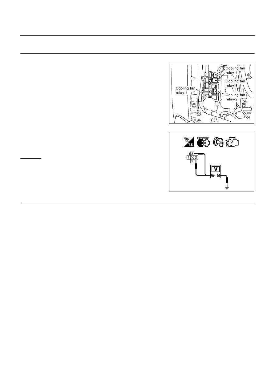
CHECK COOLING FAN POWER SUPPLY CIRCUIT

1.

Turn ignition switch OFF.

2.

Disconnect cooling fan relay-1.

3.

Turn ignition switch ON.

4.

Check voltage between cooling fan relay-1 terminals 2, 3 and
ground with CONSULT-II or tester.

OK or NG

OK

>> GO TO 3.

NG

>> GO TO 2.

2.

DETECT MALFUNCTIONING PART

Check the following.

Fuse block (J/B) connector E109

10A fuse

40A fusible link

Harness for open or short between cooling fan relay-1 and fuse

Harness for open or short between cooling fan relay-1 and battery

>> Repair open circuit or short to ground or short to power in harness or connectors.

MBIB1094E

Voltage: Battery voltage

MBIB0055E

DTC P0217 ENGINE OVER TEMPERATURE

EC-1371

[YD (WITHOUT EURO-OBD)]

C

D

E

F

G

H

I

J

K

L

M

A

EC

3.

CHECK COOLING FAN MOTORS CONTROL CIRCUIT FOR OPEN AND SHORT

1.

Turn ignition switch OFF.

2.

Disconnect cooling fan motor-1 harness connector and cooling
fan motor-2 harness connector.

3.

Disconnect cooling fan relay-2 and cooling fan relay-4.

4.

Check harness continuity between the following.

Cooling fan relay-1 terminal 5 and cooling fan motor-1 terminal 1

Cooling fan motor-1 terminal 2 and cooling fan relay-2 terminal 3

Cooling fan motor-1 terminal 2 and cooling fan relay-4 terminal 3

Cooling fan relay-2 terminal 4 and cooling fan motor-2 terminal 1

Cooling fan relay-4 terminal 4 and cooling fan motor-2 terminal 1

Cooling fan motor-2 terminal 2 and body ground
Refer to Wiring Diagram.

5.

Also check harness for short to ground and short to power.

OK or NG

OK

>> GO TO 4.

NG

>> Repair open circuit or short to ground or short to power in harness or connectors.

4.

CHECK COOLING FAN MOTOR OUTPUT SIGNAL CIRCUIT FOR OPEN AND SHORT

1.

Disconnect smart entrance control unit harness connector.

2.

Check harness continuity between cooling fan relay-1 terminal 1
and smart entrance control unit terminal 33.
Refer to Wiring Diagram.

3.

Also check harness for short to ground and short to power.

OK or NG

OK

>> GO TO 6.

NG

>> GO TO 5.

5.

DETECT MALFUNCTIONING PART

Check the following.

Harness connectors E106, M11 (LHD models)

Harness connectors E145, M80 (RHD models)

Harness for open or short between cooling fan relay-1 and smart entrance control unit

>> Repair open circuit or short to ground or short to power in harness or connectors.

6.

CHECK COOLING FAN RELAYS-1, -2 AND 4

Refer to

EC-1377, "Component Inspection"

.

OK or NG

OK

>> GO TO 7.

NG

>> Replace cooling fan relay.

Continuity should exist.

MBIB0642E

Continuity should exist.

MBIB0987E

EC-1372

[YD (WITHOUT EURO-OBD)]

DTC P0217 ENGINE OVER TEMPERATURE

7.

CHECK COOLING FAN MOTORS-1 AND -2

Refer to

EC-1377, "Component Inspection"

.

OK or NG

OK

>> GO TO 8.

NG

>> Replace cooling fan motor.

8.

CHECK SMART ENTRANCE CONTROL UNIT

Refer to EL-350, “Trouble Diagnoses”.

OK or NG

OK

>> GO TO 9.

NG

>> Replace smart entrance control unit.

9.

CHECK INTERMITTENT INCIDENT

Perform

EC-1309, "TROUBLE DIAGNOSIS FOR INTERMITTENT INCIDENT"

.

>> INSPECTION END

PROCEDURE B

1.

CHECK COOLING FAN RELAYS-2 AND -4 POWER SUPPLY CIRCUIT

1.

Turn ignition switch OFF.

2.

Disconnect cooling fan relays-2 and -4.

3.

Turn ignition switch ON.

4.

Check voltage between cooling fan relays-2, -4 terminal 1 and
ground with CONSULT-II or tester.

OK or NG

OK

>> GO TO 3.

NG

>> GO TO 2.

2.

DETECT MALFUNCTIONING PART

Check the following.

Fuse block (J/B) connector E109

Harness for open or short between cooling fan relays-2, -4 and fuse

>> Repair open circuit or short to ground or short to power in harness or connectors.

MBIB1094E

Voltage: Battery voltage

MBIB0991E

DTC P0217 ENGINE OVER TEMPERATURE

EC-1373

[YD (WITHOUT EURO-OBD)]

C

D

E

F

G

H

I

J

K

L

M

A

EC

3.

CHECK COOLING FAN RELAY GROUND CIRCUIT FOR OPEN AND SHORT

1.

Turn ignition switch OFF.

2.

Check harness continuity between cooling fan relay-2 terminal 5 and body ground, cooling fan relay-4 ter-
minal 5 and body ground.
Refer to Wiring Diagram.

3.

Also check harness for short to power.

OK or NG

OK

>> GO TO 4.

NG

>> Repair open circuit or short to power in harness or connectors.

4.

CHECK COOLING FAN MOTOR OUTPUT SIGNAL CIRCUIT FOR OPEN AND SHORT

1.

Disconnect smart entrance control unit harness connector.

2.

Check harness continuity between cooling fan relay-2 terminal 2
and smart entrance control unit terminal 32, cooling fan relay-4
terminal 2 and smart entrance control unit terminal 32.
Refer to Wiring Diagram.

3.

Also check harness for short to ground and short to power.

OK or NG

OK

>> GO TO 6.

NG

>> GO TO 5.

5.

DETECT MALFUNCTIONING PART

Check the following.

Harness connectors E106, M11 (LHD models)

Harness connectors E145, M80 (RHD models)

Harness for open or short between cooling fan relay-2 and smart entrance control unit

Harness for open or short between cooling fan relay-4 and smart entrance control unit

>> Repair open circuit or short to ground or short to power in harness or connectors.

6.

CHECK COOLING FAN RELAYS-2 AND -4

Refer to

EC-1377, "Component Inspection"

.

OK or NG

OK

>> GO TO 7.

NG

>> Replace cooling fan relay.

7.

CHECK SMART ENTRANCE CONTROL UNIT

Refer to EL-350, “Trouble Diagnoses”.

OK or NG

OK

>> GO TO 8.

NG

>> Replace smart entrance control unit.

8.

CHECK INTERMITTENT INCIDENT

Perform

EC-1309, "TROUBLE DIAGNOSIS FOR INTERMITTENT INCIDENT"

.

>> INSPECTION END

Continuity should exist.

Continuity should exist.

MBIB0987E


Content   ..  634  635  636  637   ..