Nissan Almera Tino V10. Manual - part 617
EC-1294
[YD (WITHOUT EURO-OBD)]
TROUBLE DIAGNOSIS
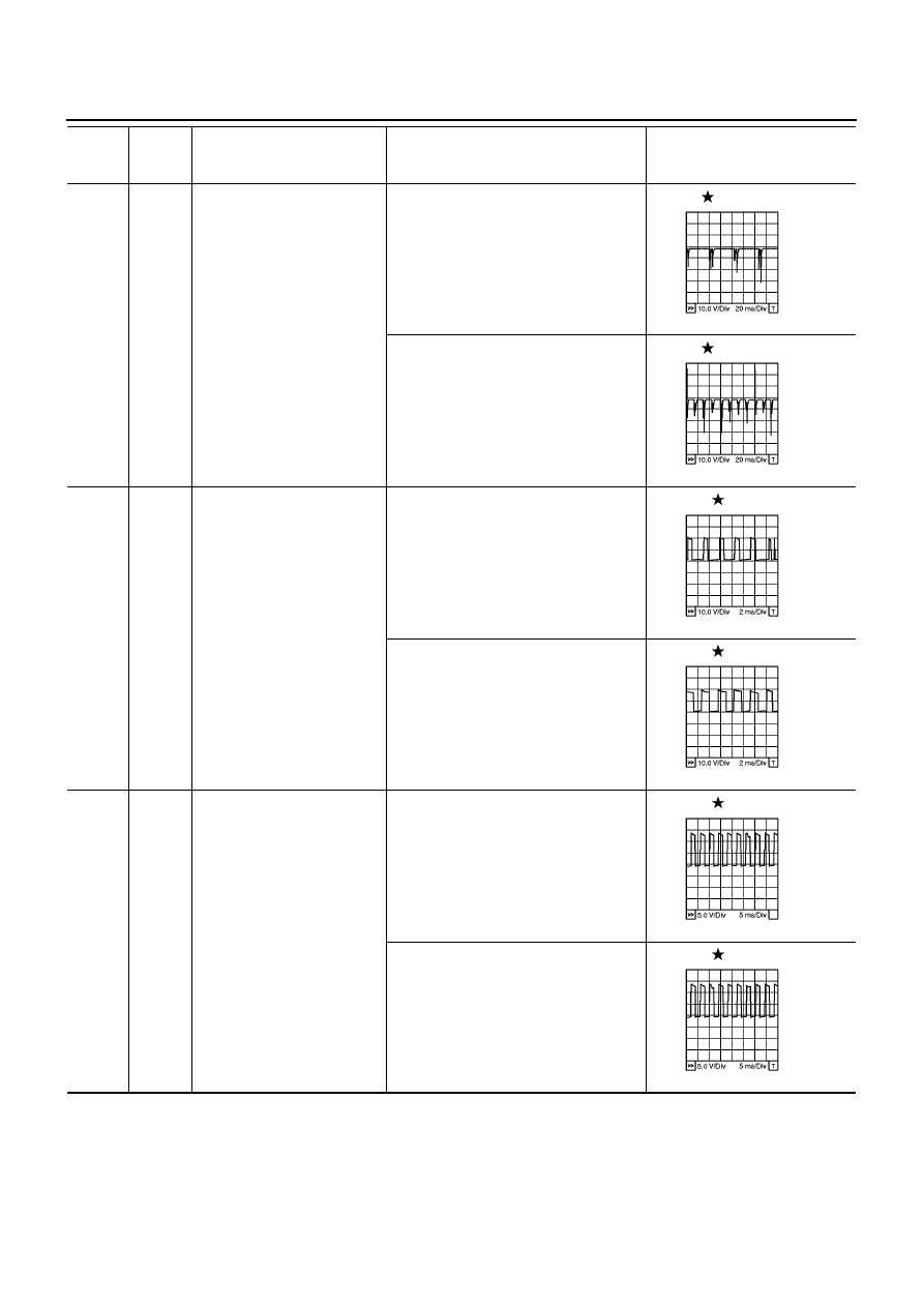
4
5
O/B
B
Fuel injector power supply
(For cylinder No. 1 and 4)
Fuel injector power supply
(For cylinder No. 2 and 3)
[Engine is running]
●
Warm-up condition
●
Idle speed
5 - 10V
[Engine is running]
●
Warm-up condition
●
Engine speed is 2,000 rpm
5 - 10V
6
L
Turbocharger boost control
solenoid valve*
2
[Ignition switch ON]
●
Warm-up condition
●
Idle speed
0 - 12.5V
[Ignition switch ON]
●
Warm-up condition
●
Engine speed is 2,000 rpm
0 - 12.5V
10
Y/L
Fuel pump power supply
[Engine is running]
●
Warm-up condition
●
Idle speed
0 - 12.5V
[Engine is running]
●
Warm-up condition
●
Engine speed is 2,000 rpm
0 - 12.5V
TERMI-
NAL
NO.
WIRE
COLOR
ITEM
CONDITION
DATA
(DC Voltage and Pulse Signal)
MBIB0883E
MBIB0884E
MBIB0889E
MBIB0890E
MBIB0885E
MBIB0886E