Nissan Almera Tino V10. Manual - part 603
EC-1238
[YD (WITH EURO-OBD)]
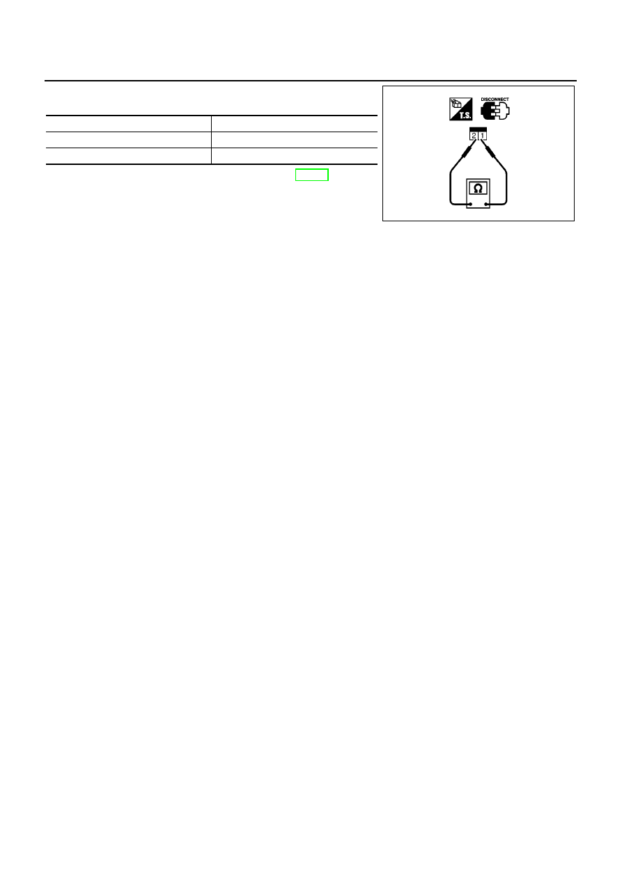
BRAKE SWITCH
2.
Check continuity between stop lamp switch terminals 1 and 2
under the following conditions.
If NG, adjust brake pedal installation, refer to BR-14, “BRAKE
PEDAL AND BRACKET”, and perform step 2 again.
Conditions
Continuity
Brake pedal fully released
Should not exist.
Brake pedal depressed
Should exist.
PBIB0118E