Nissan Almera Tino V10. Manual - part 602


  Index      Nissan     Nissan Almera Tino V10 - Service Manual (2003 year)


Search            


Content   ..  600  601  602  603   ..


Nissan Almera Tino V10. Manual - part 602


EC-1234

[YD (WITH EURO-OBD)]

BRAKE SWITCH

BRAKE SWITCH

PFP:25230

Description

EBS013HU

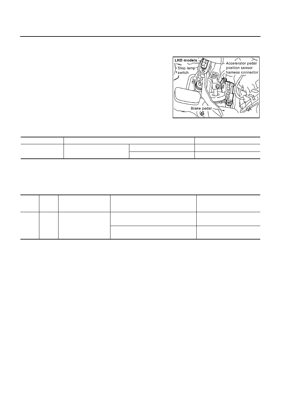
The stop lamp switch is installed to brake pedal bracket. The switch
senses brake pedal position and sends an ON-OFF signal to the
ECM. The ECM uses the signal to control the fuel injection control
system.

CONSULT-II Reference Value in Data Monitor Mode

EBS013HV

Specification data are reference values.

ECM Terminals and Reference Value

EBS013HW

Specification data are reference values and are measured between each terminal and ground.

CAUTION:

Do not use ECM ground terminals when measuring input/output voltage. Doing so may result in dam-
age to the ECM's transistor. Use a ground other than ECM terminals, such as the ground.

MBIB0903E

MONITOR ITEM

CONDITION

SPECIFICATION

BRAKE SW

Ignition switch: ON

Brake pedal: Fully released

OFF

Brake pedal: Slightly depressed

ON

TERMI-

NAL

NO.

WIRE

COLOR

ITEM

CONDITION

DATA

(DC Voltage)

100

R/G

Stop lamp switch

[Ignition switch ON]

Brake pedal: Fully released

Approximately 0V

[Ignition switch ON]

Brake pedal: Depressed

BATTERY VOLTAGE
(11 - 14V)

BRAKE SWITCH

EC-1235

[YD (WITH EURO-OBD)]

C

D

E

F

G

H

I

J

K

L

M

A

EC

Wiring Diagram

EBS013HX

YEC514A

EC-1236

[YD (WITH EURO-OBD)]

BRAKE SWITCH

Diagnostic Procedure

EBS013HY

1.

CHECK OVERALL FUNCTION

With CONSULT-II

1.

Turn ignition switch ON.

2.

Select “BRAKE SW” in “DATA MONITOR” mode with CON-
SULT-II.

3.

Check “BRAKE SW” signal under the following conditions.

Without CONSULT-II

Check voltage between ECM terminal 100 and ground under the fol-
lowing conditions.

OK or NG

OK

>> INSPECTION END

NG

>> GO TO 2.

2.

CHECK STOP LAMP SWITCH POWER SUPPLY CIRCUIT

1.

Turn ignition switch OFF.

2.

Disconnect stop lamp switch harness connector.

3.

Check voltage between stop lamp switch terminal 1 and ground
with CONSULT-II or tester.

OK or NG

OK

>> GO TO 4.

NG

>> GO TO 3.

Conditions

BRAKE SW

Brake pedal released

OFF

Brake pedal slightly depressed

ON

PBIB0472E

Condition

Voltage

Brake pedal released

Approximately 0V

Brake pedal slightly depressed

Battery voltage

MBIB1097E

MBIB0903E

Voltage: Battery voltage

PBIB0117E

BRAKE SWITCH

EC-1237

[YD (WITH EURO-OBD)]

C

D

E

F

G

H

I

J

K

L

M

A

EC

3.

DETECT MALFUNCTIONING PART

Check the following.

10A fuse

Fuse block (J/B) connector M2

Harness for open and short between stop lamp switch and battery

>> Repair open circuit or short to ground or short to power in harness or connectors.

4.

CHECK STOP LAMP SWITCH INPUT SIGNAL CIRCUIT FOR OPEN AND SHORT

1.

Disconnect ECM harness connector.

2.

Check harness continuity between ECM terminal 100 and stop lamp switch terminal 2. Refer to Wiring
Diagram.

3.

Also check harness for short to ground and short to power.

OK or NG

OK

>> GO TO 5.

NG

>> Repair open circuit or short to ground or short to power in harness or connectors.

5.

CHECK STOP LAMP SWITCH

Refer to

EC-1237, "Component Inspection"

.

OK or NG

OK

>> GO TO 6.

NG

>> Replace stop lamp switch.

6.

CHECK INTERMITTENT INCIDENT

Refer to

EC-1002, "TROUBLE DIAGNOSIS FOR INTERMITTENT INCIDENT"

.

>> INSPECTION END

Component Inspection

EBS013HZ

STOP LAMP SWITCH

1.

Disconnect stop lamp switch harness connector.

Continuity should exist.

MBIB0903E


Content   ..  600  601  602  603   ..