Nissan Almera Tino V10. Manual - part 596


  Index      Nissan     Nissan Almera Tino V10 - Service Manual (2003 year)


Search            


Content   ..  594  595  596  597   ..


Nissan Almera Tino V10. Manual - part 596


EC-1210

[YD (WITH EURO-OBD)]

DTC P2135 APP SENSOR

On Board Diagnosis Logic

EBS013GZ

This self-diagnosis has the one trip detection logic.
The MI will not light up for this self-diagnosis.

DTC Confirmation Procedure

EBS013H0

NOTE:
If DTC Confirmation Procedure has been previously conducted, always turn ignition switch OFF and wait at
least 10 seconds before conducting the next test.

WITH CONSULT-II

1.

Turn ignition switch ON.

2.

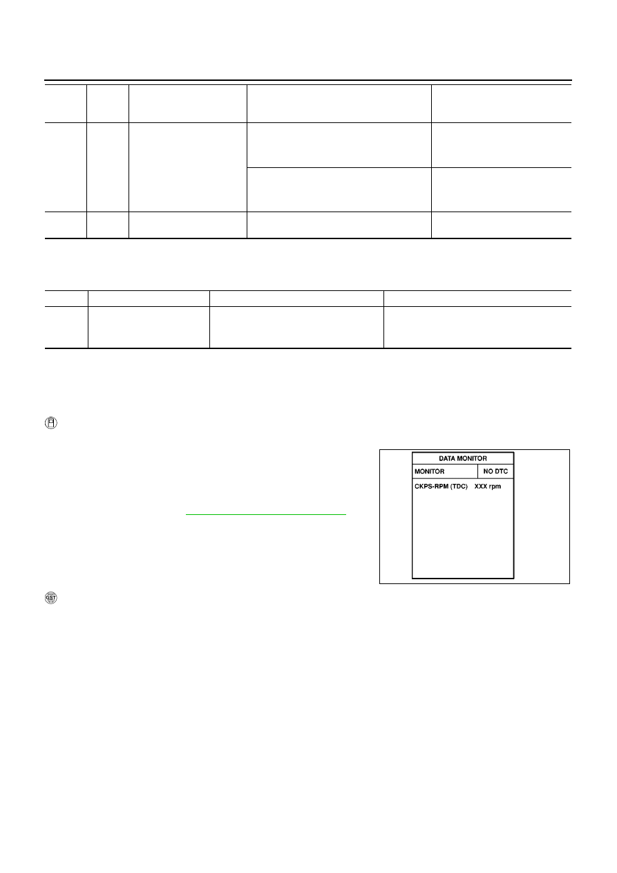
Select “DATA MONITOR” mode with CONSULT-II.

3.

Wait at least 5 seconds.

4.

Depress accelerator pedal slowly spending 5 seconds, and then
release it slowly spending 5 seconds.

5.

If DTC is detected, go to

EC-1212, "Diagnostic Procedure"

.

WITH GST

Follow the procedure “WITH CONSULT-II” above.

91

B

Accelerator pedal position
sensor 2

[Ignition switch ON]

Engine stopped

Accelerator pedal: Fully released

0.4 - 0.7V

[Ignition switch ON]

Engine stopped

Accelerator pedal: Fully depressed

2.2 - 2.7V

92

W

Accelerator pedal position
sensor 2 ground

[Ignition switch ON]

Approximately 0.3V

TERMI-

NAL

NO.

WIRE

COLOR

ITEM

CONDITION

DATA

(DC Voltage)

DTC No.

Trouble diagnosis name

DTC detecting condition

Possible cause

P2135

Accelerator pedal position
sensor 1, 2 signal correlation

The correlation between APP sensor 1
signal and APP sensor 2 signal is out of
the normal range.

Harness or connectors
(The APP sensor circuit is open or shorted.)

Accelerator pedal position sensor

SEF817Y

DTC P2135 APP SENSOR

EC-1211

[YD (WITH EURO-OBD)]

C

D

E

F

G

H

I

J

K

L

M

A

EC

Wiring Diagram

EBS013H1

YEC521A

EC-1212

[YD (WITH EURO-OBD)]

DTC P2135 APP SENSOR

Diagnostic Procedure

EBS013H2

1.

CHECK GROUND CONNECTIONS

1.

Turn ignition switch OFF.

2.

Loosen and retighten body ground screw. Refer to

EC-1010,

"Ground Inspection"

.

OK or NG

OK

>> GO TO 2.

NG

>> Repair or replace ground connection.

2.

CHECK APP SENSOR POWER SUPPLY CIRCUIT

1.

Disconnect accelerator pedal position (APP) sensor harness
connector.

2.

Turn ignition switch ON.

3.

Check voltage between APP sensor terminals 1, 2 and ground
with CONSULT-II or tester.

OK or NG

OK

>> GO TO 3.

NG

>> Repair open circuit or short to ground or short to power

in harness or connectors.

3.

CHECK APP SENSOR GROUND CIRCUIT FOR OPEN AND SHORT

1.

Turn ignition switch OFF.

2.

Disconnect ECM harness connector.

3.

Check harness continuity between APP sensor terminal 4 and ECM terminal 84, APP sensor terminal 5
and ECM terminal 92.
Refer to Wiring Diagram.

4.

Also check harness for short to ground and short to power.

OK or NG

OK

>> GO TO 4.

NG

>> Repair open circuit or short to ground or short to power in harness or connectors.

MBIB0915E

MBIB0904E

Voltage: Approximately 5.3V

PBIB0782E

Continuity should exist.

DTC P2135 APP SENSOR

EC-1213

[YD (WITH EURO-OBD)]

C

D

E

F

G

H

I

J

K

L

M

A

EC

4.

CHECK APP SENSOR INPUT SIGNAL CIRCUIT FOR OPEN AND SHORT

1.

Check harness continuity between ECM terminal 83 and APP sensor terminal 3, ECM terminal 91 and
APP sensor terminal 6.
Refer to Wiring Diagram.

2.

Also check harness for short to ground and short to power.

OK or NG

OK

>> GO TO 5.

NG

>> Repair open circuit or short to ground or short to power in harness or connectors.

5.

CHECK APP SENSOR

Refer to

EC-1213, "Component Inspection"

.

OK or NG

OK

>> GO TO 6.

NG

>> Replace accelerator pedal assembly.

6.

CHECK INTERMITTENT INCIDENT

Refer to

EC-1002, "TROUBLE DIAGNOSIS FOR INTERMITTENT INCIDENT"

.

>> INSPECTION END

Component Inspection

EBS013H3

ACCELERATOR PEDAL POSITION SENSOR

1.

Reconnect all harness connectors disconnected.

2.

Turn ignition switch ON.

3.

Check voltage between ECM terminals 83 (APP sensor 1 sig-
nal), 91 (APP sensor 2 signal) and body ground under the fol-
lowing conditions.

4.

If NG, replace accelerator pedal assembly.

Removal and Installation

EBS013H4

ACCELERATOR PEDAL

Refer to FE-16, “ACCELERATOR CONTROL SYSTEM”.

Continuity should exist.

Terminal

Accelerator pedal

Voltage

83

(Accelerator pedal position

sensor 1)

Fully released

0.5 - 1.0V

Fully depressed

4.2 - 5.2V

91
(Accelerator pedal position
sensor 2)

Fully released

0.4 - 0.7V

Fully depressed

2.2 - 2.7V

MBIB0615E


Content   ..  594  595  596  597   ..