Nissan Almera Tino V10. Manual - part 597


  Index      Nissan     Nissan Almera Tino V10 - Service Manual (2003 year)


Search            


Content   ..  595  596  597  598   ..


Nissan Almera Tino V10. Manual - part 597


EC-1214

[YD (WITH EURO-OBD)]

DTC P2146, P2149 FUEL INJECTOR POWER SUPPLY

DTC P2146, P2149 FUEL INJECTOR POWER SUPPLY

PFP:16600

Component Description
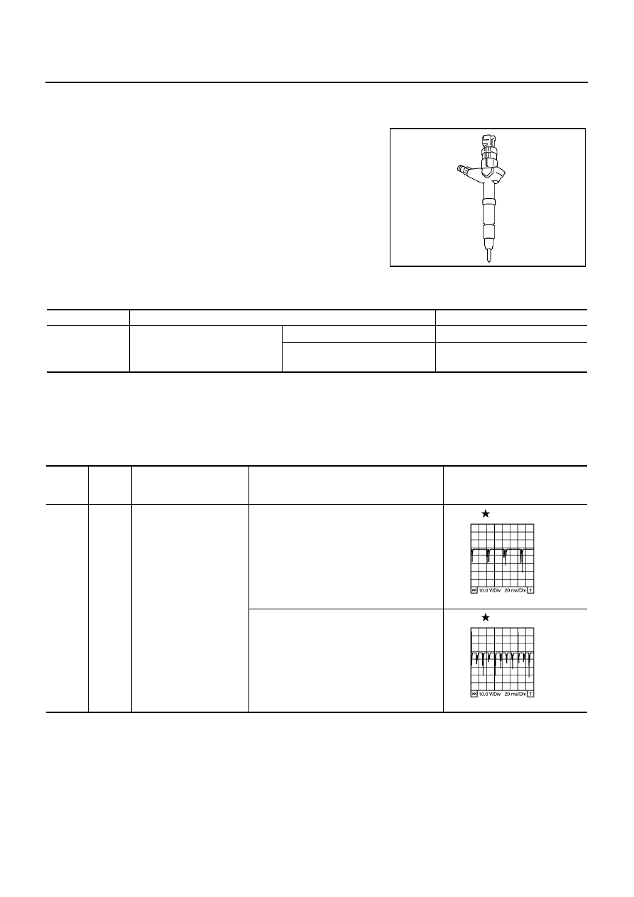
EBS013H5

The fuel injector is a small, precise solenoid valve. When the ECM
supplies a ground to the fuel injector circuit, the coil in the fuel injec-
tor is energized. The energized coil pulls the needle valve back and
allows fuel to flow through the fuel injector into the intake cylinder.
The amount of fuel injected depends upon the injection pulse dura-
tion. Pulse duration is the length of time the fuel injector remains
open. The ECM controls the injection pulse duration based on
engine fuel needs.

CONSULT-II Reference Value in Data Monitor Mode

EBS013H6

Specification data are reference values.

ECM Terminals and Reference Value

EBS013H7

Specification data are reference values and are measured between each terminal and ground.
Pulse signal is measured by CONSULT-II.

CAUTION:

Do not use ECM ground terminals when measuring input/output voltage. Doing so may result in dam-
age to the ECM's transistor. Use a ground other than ECM terminals, such as the ground.

PBIB0465E

MONITOR ITEM

CONDITION

SPECIFICATION

MAIN INJ WID

Engine: After warming up

Shift lever: Neutral position

Idle speed

No-load

0.68 - 0.78 msec

Blower fan switch: ON
Rear window defogger switch: ON

0.78 - 0.88 msec

TERMI-

NAL

NO.

WIRE

COLOR

ITEM

CONDITION

DATA

(DC Voltage and Pulse Signal)

4

5

O/B

B

Fuel injector power supply
(For cylinder No. 1 and 4)
Fuel injector power supply
(For cylinder No. 2 and 3)

[Engine is running]

Warm-up condition

Idle speed

5 - 10V

[Engine is running]

Warm-up condition

Engine speed is 2,000 rpm

5 - 10V

MBIB0883E

MBIB0884E

DTC P2146, P2149 FUEL INJECTOR POWER SUPPLY

EC-1215

[YD (WITH EURO-OBD)]

C

D

E

F

G

H

I

J

K

L

M

A

EC

: Average voltage for pulse signal (Actual pulse signal can be confirmed by oscilloscope.)

On Board Diagnosis Logic

EBS013H8

21
22
23
24

L
PU/W
L
PU/W

Fuel injector No. 2
Fuel injector No. 2
Fuel injector No. 3
Fuel injector No. 3

[Engine is running]

Warm-up condition

Idle speed

0 - 9V

[Engine is running]

Warm-up condition

Engine speed is 2,000 rpm

0 - 9V

40
41
42
43

B/P
PU/W
B/P
PU/W

Fuel injector No. 4
Fuel injector No. 4
Fuel injector No. 1
Fuel injector No. 1

[Engine is running]

Warm-up condition

Idle speed

0 - 9V

[Engine is running]

Warm-up condition

Engine speed is 2,000 rpm

0 - 9V

TERMI-

NAL

NO.

WIRE

COLOR

ITEM

CONDITION

DATA

(DC Voltage and Pulse Signal)

MBIB0881E

MBIB0882E

MBIB0881E

MBIB0882E

DTC No.

Trouble diagnosis name

DTC detecting condition

Possible cause

P2146

No. 1 and 4 cylinder fuel injector
power supply circuit open

An improper voltage signal is sent to ECM
through No. 1 and 4 cylinder fuel injector.

Harness or connectors
(The fuel injector circuit is open.)

P2149

No. 2 and 3 cylinder fuel injector
power supply circuit open

An improper voltage signal is sent to ECM
through No. 2 and 3 cylinder fuel injector.

EC-1216

[YD (WITH EURO-OBD)]

DTC P2146, P2149 FUEL INJECTOR POWER SUPPLY

DTC Confirmation Procedure

EBS013H9

NOTE:
If DTC Confirmation Procedure has been previously conducted, always turn ignition switch OFF and wait at
least 10 seconds before conducting the next test.
TESTING CONDITION
Before performing the following procedure, confirm the ambient temperature is more than -20

°

C (-4

°

F).

WITH CONSULT-II

1.

Turn ignition switch ON.

2.

Select “DATA MONITOR” mode with CONSULT-II.

3.

Start engine and let it idle for at least 5 seconds.

4.

If 1st trip DTC is detected, go to

EC-1218, "Diagnostic Proce-

dure"

.

WITH GST

Follow the procedure “WITH CONSULT-II” above.

SEF817Y

DTC P2146, P2149 FUEL INJECTOR POWER SUPPLY

EC-1217

[YD (WITH EURO-OBD)]

C

D

E

F

G

H

I

J

K

L

M

A

EC

Wiring Diagram

EBS013HA

MBWA0632E


Content   ..  595  596  597  598   ..