Nissan Almera Tino V10. Manual - part 570
EC-1106
[YD (WITH EURO-OBD)]
DTC P0335 CKP SENSOR
DTC P0335 CKP SENSOR
PFP:23731
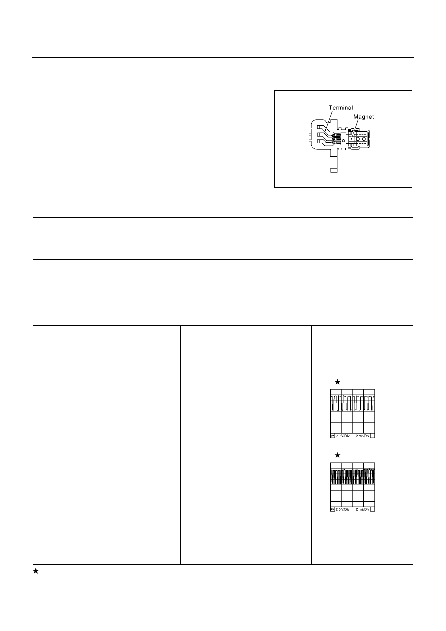
Description
EBS013CE
The crankshaft position sensor monitors engine speed by means of
signals from the sensing plate (with 56 protrusions) installed to the
fly wheel. The datum signal output is detected 6
°
signal and sent to
the ECM. The sensor signal is used for fuel injection control and fuel
injection timing control.
CONSULT-II Reference Value in Data Monitor Mode
EBS013CF
Specification data are reference values.
ECM Terminals and Reference Value
EBS013CG
Specification data are reference values and are measured between each terminal and ground.
Pulse signal is measured by CONSULT-II.
CAUTION:
Do not use ECM ground terminals when measuring input/output voltage. Doing so may result in dam-
age to the ECM's transistor. Use a ground other than ECM terminals, such as the ground.
: Average voltage for pulse signal (Actual pulse signal can be confirmed by oscilloscope.)
*1: For YD22DDT engine models
*2: For YD22DDTi engine models
MBIB0619E
MONITOR ITEM
CONDITION
SPECIFICATION
CKPS-RPM (TDC)
●
Tachometer: Connect
●
Run engine and compare CONSULT-II value with the tachometer
indication.
Almost the same speed as the
tachometer indication
TERMI-
NAL
NO.
WIRE
COLOR
ITEM
CONDITION
DATA
(DC Voltage and Pulse Signal)
44
L*
1
L/R*
2
Crankshaft position sensor
power supply
[Ignition switch ON]
Approximately 5.3V
46
L/W*
1
L/G*
2
Crankshaft position sensor
[Engine is running]
●
Warm-up condition
●
Idle speed
0 - 6V
[Engine is running]
●
Warm-up condition
●
Engine speed is 2,000 rpm
0 - 6V
65
L/R*
1
L/G*
2
Crankshaft position sensor
ground
[Ignition switch ON]
Approximately 0.3V
67
B
Sensor ground
(Sensors shield circuit)
[Ignition switch ON]
Approximately 0.3V
MBIB0879E
MBIB0880E