Nissan Almera Tino V10. Manual - part 563


  Index      Nissan     Nissan Almera Tino V10 - Service Manual (2003 year)


Search            


Content   ..  561  562  563  564   ..


Nissan Almera Tino V10. Manual - part 563


EC-1078

[YD (WITH EURO-OBD)]

DTC P0217 ENGINE OVER TEMPERATURE

5.

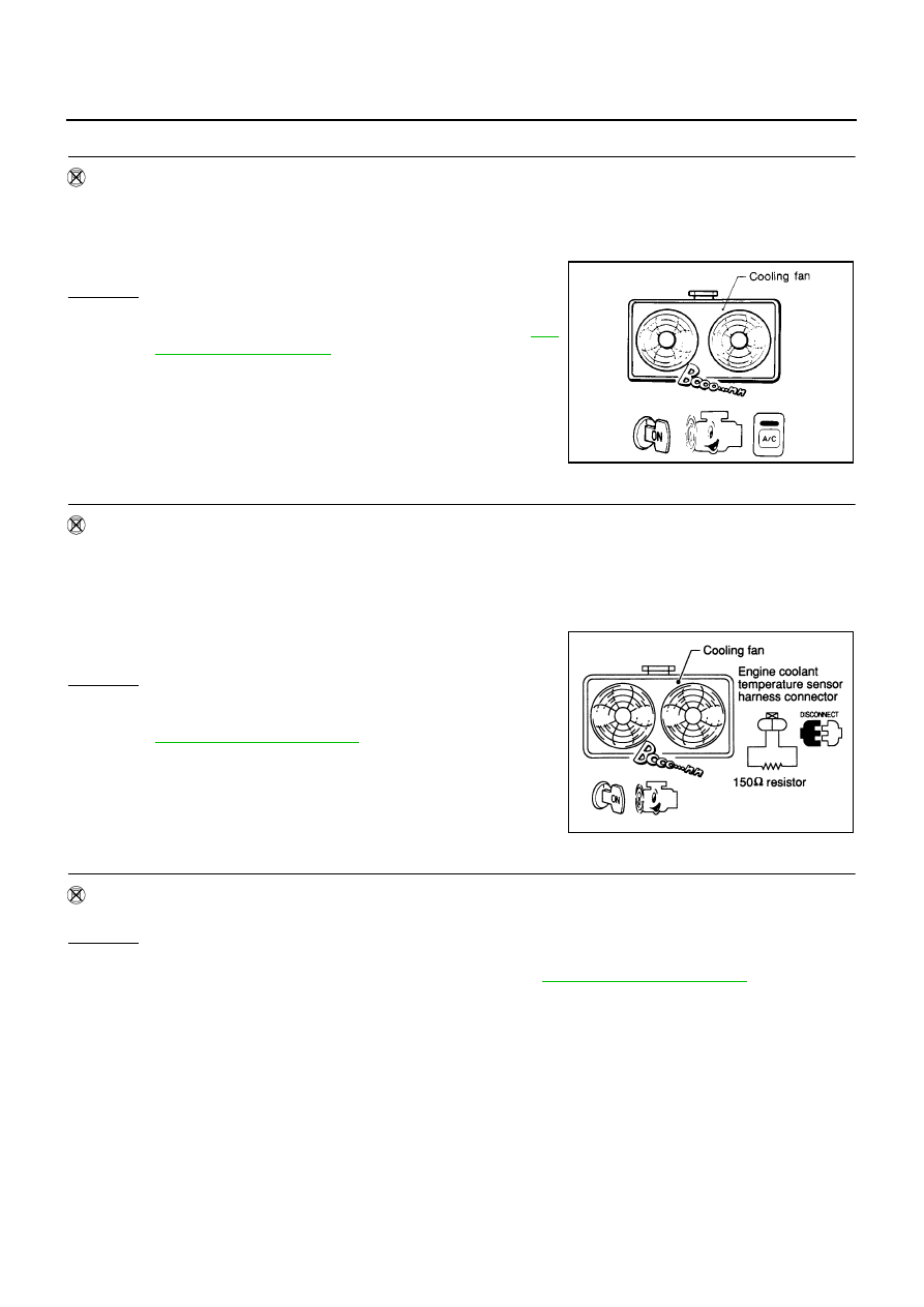
CHECK COOLING FAN LOW SPEED OPERATION

Without CONSULT-II

1.

Start engine and let it idle.

2.

Turn air conditioner switch ON.

3.

Turn blower fan switch ON.

4.

Make sure that cooling fans-1 and -2 operate at low speed.

OK or NG

OK

>> GO TO 6.

NG

>> Check cooling fan low speed control circuit. (Go to

EC-

1080, "PROCEDURE A"

.)

6.

CHECK COOLING FAN HIGH SPEED OPERATION-I

Without CONSULT-II

1.

Turn ignition switch OFF.

2.

Turn air conditioner switch and blower fan switch OFF.

3.

Disconnect engine coolant temperature sensor harness connector.

4.

Connect 150

resistor to engine coolant temperature sensor harness connector.

5.

Restart engine and make sure that cooling fan-1 operates at
higher speed than low speed.

OK or NG

OK

>> GO TO 7.

NG

>> Check cooling fan high speed control circuit-1. (Go to

EC-1082, "PROCEDURE B"

.)

7.

CHECK COOLING FAN HIGH SPEED OPERATION-II

Without CONSULT-II

Make sure that cooling fan-2 operates higher speed than lower speed.
OK or NG

OK

>> GO TO 8.

NG

>> Check cooling fan high speed control circuit-2. (Go to

EC-1084, "PROCEDURE C"

.)

SEC163BA

MEC475B

DTC P0217 ENGINE OVER TEMPERATURE

EC-1079

[YD (WITH EURO-OBD)]

C

D

E

F

G

H

I

J

K

L

M

A

EC

8.

CHECK COOLING SYSTEM FOR LEAK

Apply pressure to the cooling system with a tester, and check if the pressure drops.

CAUTION:

Higher than the specified pressure may cause radiator damage.

OK or NG

OK

>> GO TO 10.

NG

>> GO TO 9.

9.

DETECT MALFUNCTIONING PART

Check the following for leak.

Hose

Radiator

Water pump (Refer to LC-35, “Water Pump”.)

>> Repair or replace.

10.

CHECK RADIATOR CAP

Apply pressure to cap with a tester and check radiator cap relief
pressure.

OK or NG

OK

>> GO TO 11.

NG

>> Replace radiator cap.

11.

CHECK THERMOSTAT

1.

Remove thermostat.

2.

Check valve seating condition at normal room temperatures.
It should seat tightly.

3.

Check valve opening temperature and valve lift.

4.

Check if valve is closed at 5

°

C (9

°

F) below valve opening tem-

perature. For details, refer to LC-37, “Thermostat”.

OK or NG

OK

>> GO TO 12.

NG

>> Replace thermostat.

Testing pressure: 157 kPa (1.57 bar, 1.6 kg/cm

2

, 23psi)

Pressure should not drop.

SLC754A

Radiator cap relief pressure:

59 - 98 kPa (0.59 - 0.98 bar, 0.6 - 1.0 kg/cm

2

, 9 - 14

psi)

SLC755A

Valve opening temperature:

80.5 - 83.5

°

C (177 - 182

°

F)

Valve lift:

More than 8 mm/95

°

C (0.31 in/203

°

F)

SLC343

EC-1080

[YD (WITH EURO-OBD)]

DTC P0217 ENGINE OVER TEMPERATURE

12.

CHECK ENGINE COOLANT TEMPERATURE SENSOR

Refer to

EC-1049, "Component Inspection"

.

OK or NG

OK

>> GO TO 13.

NG

>> Replace engine coolant temperature sensor.

13.

CHECK MAIN 12 CAUSES

If the cause cannot be isolated, go to

EC-1086, "Main 12 Causes of Overheating"

.

>> INSPECTION END

PROCEDURE A

1.

CHECK COOLING FAN POWER SUPPLY CIRCUIT

1.

Turn ignition switch OFF.

2.

Disconnect cooling fan relay-1.

3.

Turn ignition switch ON.

4.

Check voltage between cooling fan relay-1 terminals 2, 3 and
ground with CONSULT-II or tester.

OK or NG

OK

>> GO TO 3.

NG

>> GO TO 2.

2.

DETECT MALFUNCTIONING PART

Check the following.

Fuse block (J/B) connector E109

10A fuse

40A fusible link

Harness for open or short between cooling fan relay-1 and fuse

Harness for open or short between cooling fan relay-1 and battery

>> Repair open circuit or short to ground or short to power in harness or connectors.

MBIB1094E

Voltage: Battery voltage

MBIB0055E

DTC P0217 ENGINE OVER TEMPERATURE

EC-1081

[YD (WITH EURO-OBD)]

C

D

E

F

G

H

I

J

K

L

M

A

EC

3.

CHECK COOLING FAN MOTORS CONTROL CIRCUIT FOR OPEN AND SHORT

1.

Turn ignition switch OFF.

2.

Disconnect cooling fan motor-1 harness connector and cooling
fan motor-2 harness connector.

3.

Disconnect cooling fan relay-2 and cooling fan relay-4.

4.

Check harness continuity between the following.

Cooling fan relay-1 terminal 5 and cooling fan motor-1 terminal 1

Cooling fan motor-1 terminal 2 and cooling fan relay-2 terminal 3

Cooling fan motor-1 terminal 2 and cooling fan relay-4 terminal 3

Cooling fan relay-2 terminal 4 and cooling fan motor-2 terminal 1

Cooling fan relay-4 terminal 4 and cooling fan motor-2 terminal 1

Cooling fan motor-2 terminal 2 and body ground
Refer to Wiring Diagram.

5.

Also check harness for short to ground and short to power.

OK or NG

OK

>> GO TO 4.

NG

>> Repair open circuit or short to ground or short to power in harness or connectors.

4.

CHECK COOLING FAN MOTOR OUTPUT SIGNAL CIRCUIT FOR OPEN AND SHORT

1.

Disconnect smart entrance control unit harness connector.

2.

Check harness continuity between cooling fan relay-1 terminal 1
and smart entrance control unit terminal 33.
Refer to Wiring Diagram.

3.

Also check harness for short to ground and short to power.

OK or NG

OK

>> GO TO 6.

NG

>> GO TO 5.

5.

DETECT MALFUNCTIONING PART

Check the following.

Harness connectors E106, M11 (LHD models)

Harness connectors E145, M80 (RHD models)

Harness for open or short between cooling fan relay-1 and smart entrance control unit

>> Repair open circuit or short to ground or short to power in harness or connectors.

6.

CHECK COOLING FAN RELAYS-1, -2 AND 4

Refer to

EC-1087, "Component Inspection"

.

OK or NG

OK

>> GO TO 7.

NG

>> Replace cooling fan relay.

Continuity should exist.

MBIB0642E

Continuity should exist.

MBIB0987E


Content   ..  561  562  563  564   ..