Nissan Almera Tino V10. Manual - part 561
EC-1070
[YD (WITH EURO-OBD)]
DTC P0201 - P0204 FUEL INJECTOR
Diagnostic Procedure
EBS013BD
1.
CHECK FUEL INJECTOR POWER SUPPLY FOR OPEN AND SHORT CIRCUIT
1.
Turn ignition switch OFF.
2.
Disconnect ECM harness connector.
3.
Disconnect fuel injector harness connector.
4.
Check harness continuity between the following terminals corre-
sponding to the malfunctioning cylinder. Refer to Wiring Dia-
gram.
5.
Also check harness for short to ground and short to power.
OK or NG
OK
>> GO TO 2.
NG
>> Repair open circuit or short to ground or short to power in harness or connectors.
2.
CHECK FUEL INJECOR OUTPUT SIGNAL CIRCUIT FOR OPEN AND SHORT
1.
Check harness continuity between the following terminals corresponding to the malfunctioning cylinder.
Refer to Wiring Diagram.
2.
Also check harness for short to ground and short to power.
OK or NG
OK
>> GO TO 3.
NG
>> Repair open circuit or short to ground or short to power in harness or connectors.
3.
CHECK FUEL INJECTOR-I
Refer to
EC-1071, "Component Inspection"
.
OK or NG
OK
>> GO TO 4.
NG
>> Replace fuel injector.
DTC
Terminal
Cylinder
ECM
Fuel injector
P0201
4
3
No.1
P0202
5
3
No.2
P0203
5
3
No.3
P0204
4
3
No.4
Continuity should exist.
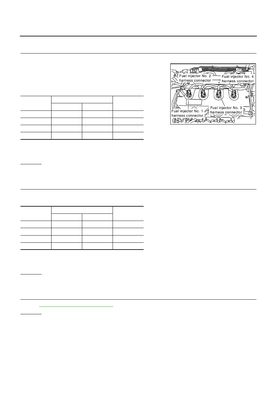
MBIB0635E
DTC
Terminal
Cylinder
ECM
Fuel injector
P0201
42, 43
4
No.1
P0202
21, 22
4
No.2
P0203
23, 24
4
No.3
P0204
40, 41
4
No.4
Continuity should exist.