Nissan Almera Tino V10. Manual - part 545
EC-1006
[YD (WITH EURO-OBD)]
MAIN POWER SUPPLY AND GROUND CIRCUIT
5.
CHECK ECM GROUND CIRCUIT FOR OPEN AND SHORT
1.
Disconnect ECM harness connector.
2.
Check harness continuity between ECM terminals 1, 2, 3, 114 and body ground.
Refer to Wiring Diagram.
3.
Also check harness for short to power.
OK or NG
OK
>> GO TO 7.
NG
>> GO TO 6.
6.
DETECT MALFUNCTIONING PART
Check the following.
●
Harness connectors M71, F45
●
Harness for open or short between ECM and body ground
>> Repair open circuit or short to power in harness or connectors.
7.
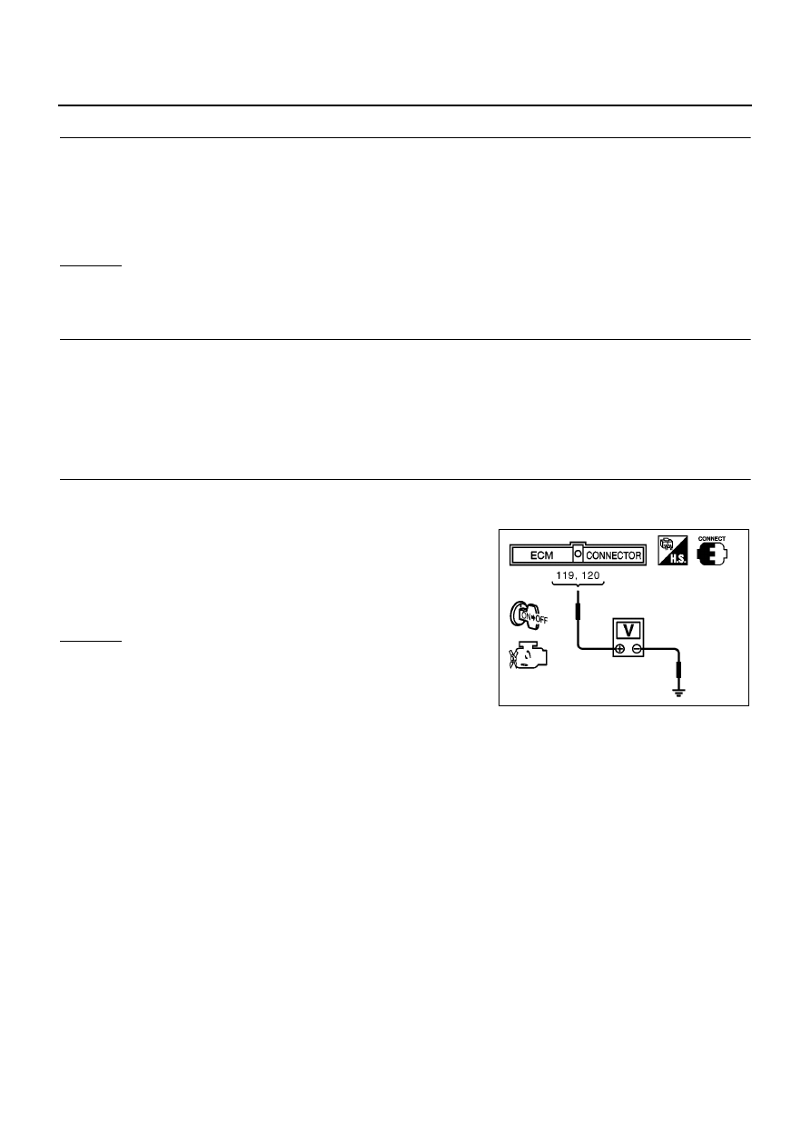
CHECK ECM POWER SUPPLY CIRCUIT-II
1.
Reconnect ECM harness connector.
2.
Turn ignition switch ON and then OFF.
3.
Check voltage between ECM terminals 119, 120 and ground
with CONSULT-II or tester.
OK or NG
OK
>> GO TO 13.
NG (Battery voltage does not exist)>>GO TO 8.
NG (Battery voltage exists for more then a few seconds)>>GO TO
10.
Continuity should exist.
Voltage:
After turning ignition switch OFF, battery
voltage will exist for a few seconds, then
drop to approximately 0V.
MBIB0611E