Index Nissan Nissan Almera Tino V10 - Service Manual (2003 year)
Search
Content .. 520 521 522 523 ..
Nissan Almera Tino V10. Manual - part 522
EC-914
[QG (WITHOUT EURO-OBD)]
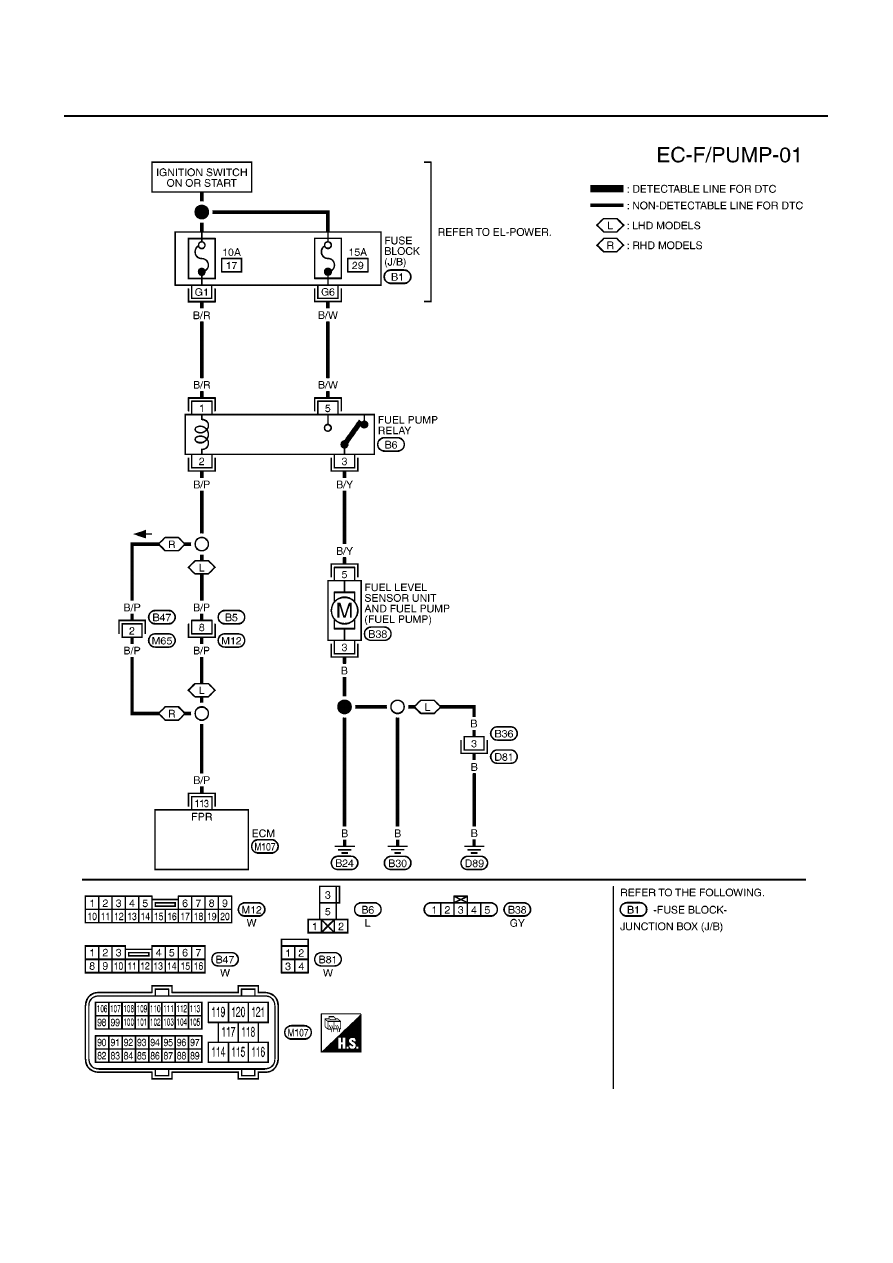
FUEL PUMP CIRCUIT
Wiring Diagram
EBS00R3U
YEC475A