Nissan Almera Tino V10. Manual - part 495
EC-806
[QG (WITHOUT EURO-OBD)]
DTC P1227, P1228 APP SENSOR
6.
REPLACE APP SENSOR
1.
Replace the accelerator pedal position sensor.
2.
Perform
EC-576, "Accelerator Pedal Released Position Learning"
.
3.
Perform
EC-576, "Throttle Valve Closed Position Learning"
.
4.
Perform
EC-576, "Idle Air Volume Learning"
.
>> INSPECTION END
7.
CHECK INTERMITTENT INCIDENT
Refer to
EC-644, "TROUBLE DIAGNOSIS FOR INTERMITTENT INCIDENT"
.
>> INSPECTION END
Component Inspection
EBS00R10
ACCELERATOR PEDAL POSITION SENSOR
1.
Reconnect all harness connectors disconnected.
2.
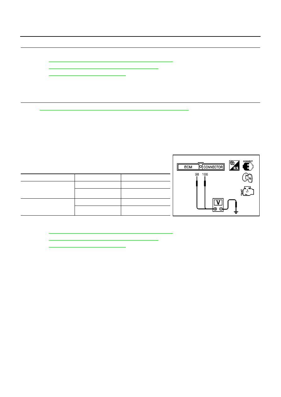
Turn ignition switch “ON”.
3.
Check voltage between ECM terminals 106 (APP sensor 1 sig-
nal), 98 (APP sensor 2 signal) and engine ground under the fol-
lowing conditions.
4.
If NG, replace accelerator pedal assembly and go to the next
step.
5.
Perform
EC-576, "Accelerator Pedal Released Position Learning"
.
6.
Perform
EC-576, "Throttle Valve Closed Position Learning"
.
7.
Perform
EC-576, "Idle Air Volume Learning"
.
Remove and Installation
EBS00R11
ACCELERATOR PEDAL
Refer to “ACCELERATOR CONTROL SYSTEM”, FE-3.
Terminal
Accelerator pedal
Voltage
106
(Accelerator pedal position
sensor 1)
Fully released
0.35 - 0.67V
Fully depressed
More than 3.9V
98
(Accelerator pedal position
sensor 2)
Fully released
0.17 - 0.34V
Fully depressed
More than 1.95V
MBIB0023E