Nissan Almera Tino V10. Manual - part 435
EC-566
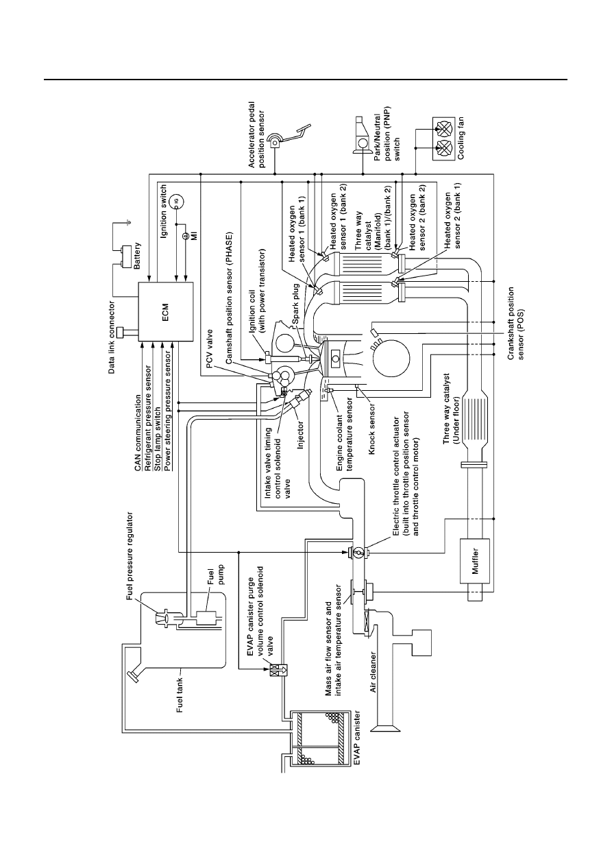
[QG (WITHOUT EURO-OBD)]
ENGINE CONTROL SYSTEM
System Diagram - A/T Models
EBS00QUO
MBIB0240E
|
|
|
EC-566 [QG (WITHOUT EURO-OBD)] ENGINE CONTROL SYSTEM System Diagram - A/T Models EBS00QUO MBIB0240E |