Nissan Almera Tino V10. Manual - part 433
EC-558
[QG (WITHOUT EURO-OBD)]
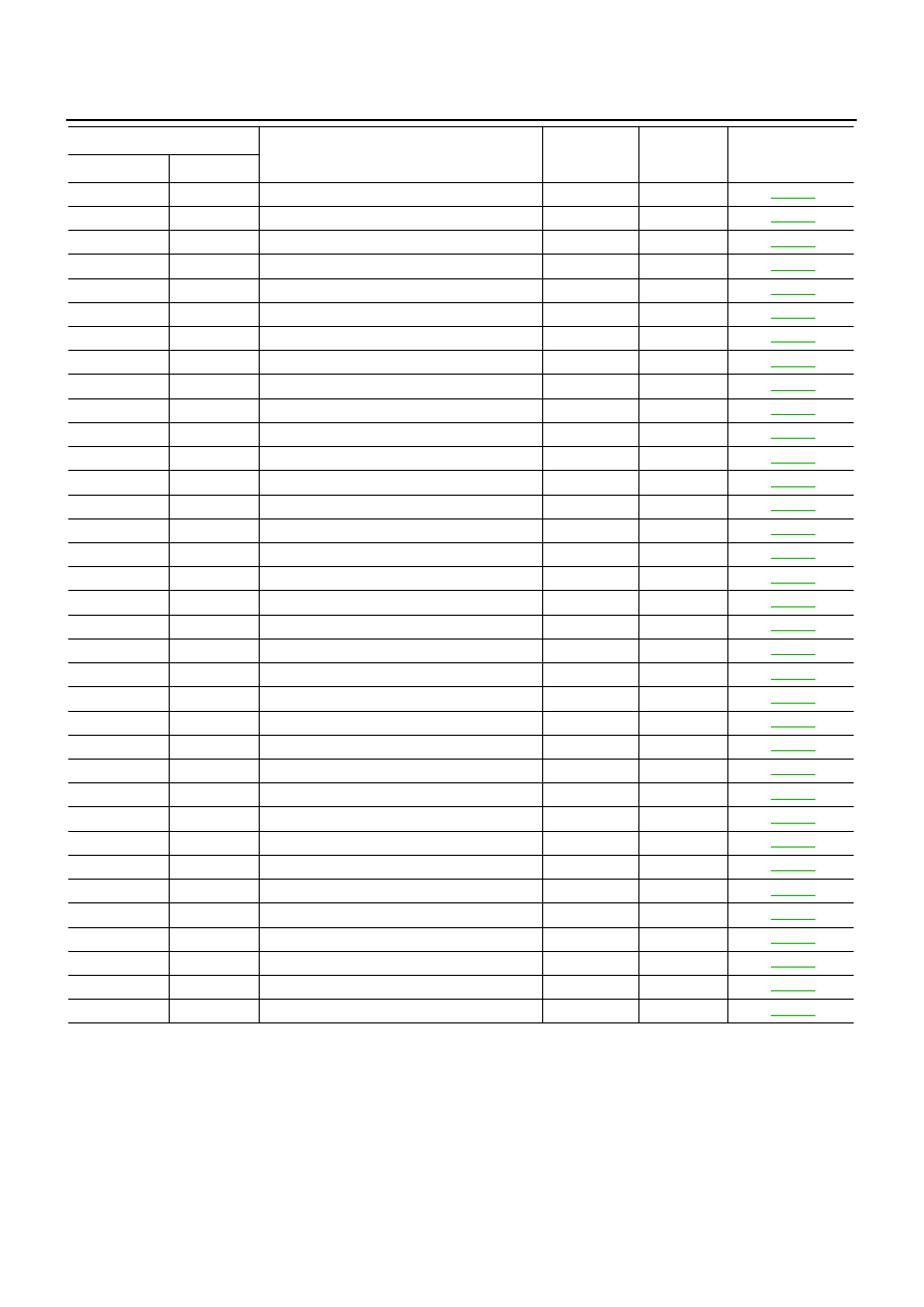
INDEX FOR DTC
*1: 1st trip DTC No. is the same as DTC No.
*2: In Diagnostic Test Mode II (Self-diagnostic results), these numbers are controlled by NISSAN.
*3: When engine is running.
*4: The troubleshooting for this DTC needs CONSULT-II.
NOTE:
Regarding V10 models with A/T, “B1” indicates bank 1 (cylinders number 1 and 4), “B2” indicates bank 2 (cylinders number 2 and 3).
P0117
0117
ECT SEN/CIRCUIT
2
×
P0118
0118
ECT SEN/CIRCUIT
2
×
P0132
0132
HO2S1 (B1)
2
×
P0134
0134
HO2S1 (B1)
2
×
P0138
0138
HO2S2 (B1)
2
×
P0152
0152
HO2S1 (B2)
2
×
P0154
0154
HO2S1 (B2)
2
×
P0158
0158
HO2S2 (B2)
2
×
P0221
0221
TP SENSOR
1
×
P0222
0222
TP SEN 1/CIRC
1
×
P0223
0223
TP SEN 1/CIRC
1
×
P0226
0226
APP SENSOR
1
×
P0227
0227
APP SEN 1/CIRC
1
×
P0228
0228
APP SEN 1/CIRC
1
×
P0327
0327
KNOCK SEN/CIRC-B1
2
—
P0328
0328
KNOCK SEN/CIRC-B1
2
—
P0335
0335
CKP SEN/CIRCUIT
2
×
P0340
0340
CMP SEN/CIRC-B1
2
×
P0605
0605
ECM
1 or 2
×
or —
P1065
1065
ECM BACK UP/CIRC
2
×
P1121
1121
ETC ACTR
1 or 2
×
P1122
1122
ETC FUNCTION/CIRC
1
×
P1124
1124
ETC MOT PWR
1
×
P1126
1126
ETC MOT PWR
1
×
P1128
1128
ETC MOT
1
×
P1217
1217
ENG OVER TEMP
1
×
P1223
1223
TP SEN 2/CIRC
1
×
P1224
1224
TP SEN 2/CIRC
1
×
P1225
1225
CTP LEARNING
2
—
P1226
1226
CTP LEARNING
2
—
P1227
1227
APP SEN 2/CIRC
1
×
P1228
1228
APP SEN 2/CIRC
1
×
P1229
1229
SENSOR POWER/CIRC
1
×
P1610 - P1615
1610 - 1615
NATS MALFUNCTION
2
—
P1805
1805
BRAKE SW/CIRCUIT
1
×
DTC
*1
Items
(CONSULT-II screen terms)
Trip
MI lighting
up
Reference page
CONSULT-II
ECM
*2