Nissan Almera Tino V10. Manual - part 395
EC-406
[QG (WITH EURO-OBD)]
DTC P1128 THROTTLE CONTROL MOTOR
Specification data are reference values and are measured between each terminal and ground.
CAUTION:
Do not use ECM ground terminals when measuring input/output voltage. Doing so may result in dam-
age to the ECM's transistor. Use a ground other than ECM terminals, such as the ground.
: Average voltage for pulse signal (Actual pulse signal can be confirmed by oscilloscope.)
Diagnostic Procedure
EBS00QPK
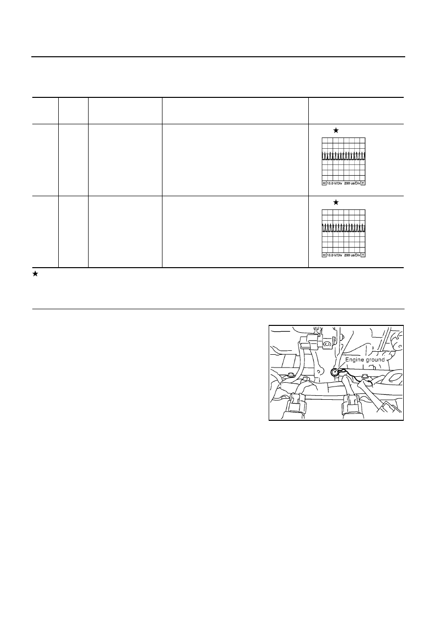
1.
RETIGHTEN GROUND SCREWS
1.
Turn ignition switch “OFF”.
2.
Loosen and retighten engine ground screws.
>> GO TO 2.
TER-
MINAL
NO.
WIRE
COLOR
ITEM
CONDITION
DATA (DC Voltage)
4
W
Throttle control motor
(Close)
[Ignition switch “ON”]
●
Engine stopped
●
Shift lever position is “D” (A/T models)
●
Shift lever position is “1st” (M/T models)
●
Accelerator pedal is releasing
0 - 14V
5
B
Throttle control motor
(Open)
[Ignition switch “ON”]
●
Engine stopped
●
Shift lever position is “D” (A/T models)
●
Shift lever position is “1st” (M/T models)
●
Accelerator pedal is depressing
0 - 14V
PBIB0534E
PBIB0533E
MBIB0095E