Nissan Almera Tino V10. Manual - part 396


  Index      Nissan     Nissan Almera Tino V10 - Service Manual (2003 year)


Search            


Content   ..  394  395  396  397   ..


Nissan Almera Tino V10. Manual - part 396


EC-410

[QG (WITH EURO-OBD)]

DTC P1143 HO2S1 (M/T MODELS)

DTC Confirmation Procedure

EBS00QPQ

CAUTION:

Always drive vehicle at a safe speed.
NOTE:
If “DTC Confirmation Procedure” has been previously conducted, always turn ignition switch “OFF” and wait at
least 10 seconds before conducting the next test.

TESTING CONDITION:

Always perform at a temperature above

10

°

C (14

°

F).

Before performing following procedure, confirm that battery voltage is more than 11V at idle.

WITH CONSULT-II

1.

Start engine and warm it up to normal operating temperature.

2.

Stop engine and wait at least 10 seconds.

3.

Turn ignition switch “ON” and select “HO2S1 (B1) P1143” of “HO2S1” in “DTC WORK SUPPORT” mode
with CONSULT-II.

4.

Touch “START”.

5.

Start engine and let it idle for at least 3 minutes.

NOTE:
Never raise engine speed above 3,600 rpm after this step. If
the engine speed limit is exceeded, return to step 5.
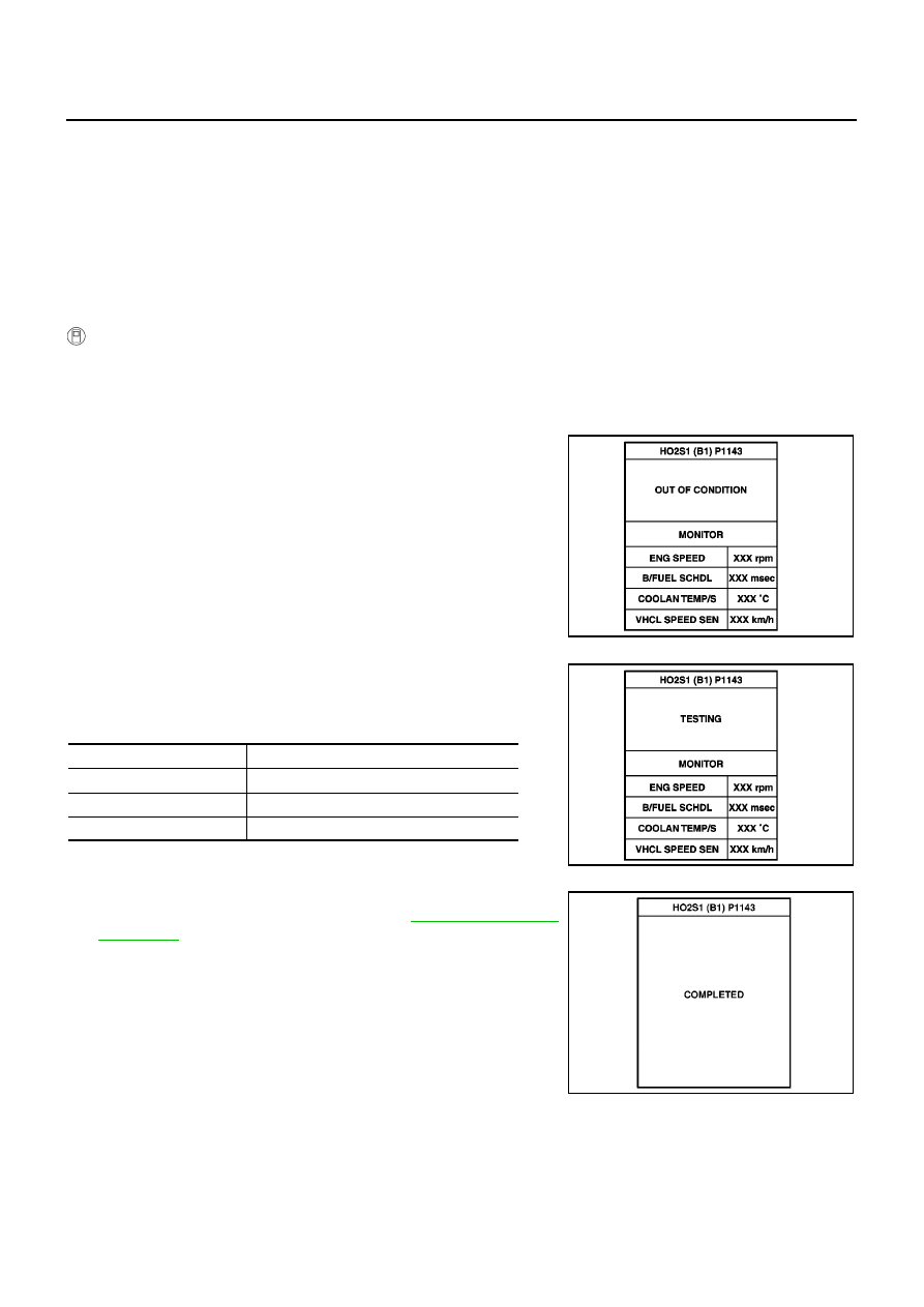
6.

When the following conditions are met, “TESTING” will be dis-
played on the CONSULT-II screen. Maintain the conditions con-
tinuously until “TESTING” changes to “COMPLETED”. (It will
take approximately 50 seconds or more.)

If “TESTING” is not displayed after 5 minutes, retry from
step 2.

7.

Make sure that “OK” is displayed after touching “SELF-DIAG
RESULTS”. If “NG” is displayed, refer to

EC-411, "Diagnostic

Procedure"

.

PBIB0546E

ENG SPEED

1,700 - 2,600 rpm

Vehicle speed

50 - 100 km/h (30 - 62 MPH)

B/FUEL SCHDL

3.0 - 5.2 msec

Selector lever

Suitable position

PBIB0547E

SEC769C

DTC P1143 HO2S1 (M/T MODELS)

EC-411

[QG (WITH EURO-OBD)]

C

D

E

F

G

H

I

J

K

L

M

A

EC

Overall Function Check

EBS00QPR

Use this procedure to check the overall function of the heated oxygen sensor 1 circuit. During this check, a
DTC might not be confirmed.

WITH GST

1.

Start engine and warm it up to normal operating temperature.

2.

Set voltmeter probes between ECM terminal 35 (HO2S1 signal) and engine ground.

3.

Check one of the following with engine speed held at 2,000 rpm
constant under no load.

The maximum voltage is over 0.6V at least one time.

The minimum voltage is over 0.1V at least one time.

4.

If NG, go to

EC-411, "Diagnostic Procedure"

.

Diagnostic Procedure

EBS00QPS

1.

RETIGHTEN GROUND SCREWS

1.

Turn ignition switch “OFF”.

2.

Loosen and retighten engine ground screws.

>> GO TO 2.

2.

RETIGHTEN HEATED OXYGEN SENSOR 1

Loosen and retighten heated oxygen sensor 1.

>> GO TO 3.

MBIB0018E

MBIB0095E

Tightening torque: 40 - 60 N·m (4.1 - 6.2 kg-m, 30 - 44 ft-lb)

MBIB0098E

EC-412

[QG (WITH EURO-OBD)]

DTC P1143 HO2S1 (M/T MODELS)

3.

CLEAR THE SELF-LEARNING DATA

With CONSULT-II

1.

Start engine and warm it up to normal operating temperature.

2.

Select “SELF-LEARNING CONT” in “WORK SUPPORT” mode with CONSULT-II.

3.

Clear the self-learning control coefficient by touching “CLEAR”.

4.

Run engine for at least 10 minutes at idle speed.
Is the 1st trip DTC P0171 detected?
Is it difficult to start engine?

Without CONSULT-II

1.

Start engine and warm it up to normal operating temperature.

2.

Turn ignition switch “OFF”.

3.

Disconnect mass air flow sensor harness connector, and restart
and run engine for at least 5 seconds at idle speed.

4.

Stop engine and reconnect mass air flow sensor harness con-
nector.

5.

Make sure that DTC P0102 is displayed.

6.

Erase the DTC memory. Refer to

EC-68, "HOW TO ERASE

EMISSION-RELATED DIAGNOSTIC INFORMATION"

.

7.

Make sure that DTC P0000 is displayed.

8.

Run engine for at least 10 minutes at idle speed.
Is the 1st trip DTC P0171 detected?
Is it difficult to start engine?

Yes or No

Yes

>> Perform trouble diagnosis for DTC P0171. Refer to

EC-281

.

No

>> GO TO 4.

4.

CHECK HEATED OXYGEN SENSOR 1 HEATER

Refer to

EC-156, "Component Inspection"

.

OK or NG

OK

>> GO TO 5.

NG

>> Replace heated oxygen sensor 1.

5.

CHECK HEATED OXYGEN SENSOR 1

Refer to

EC-413, "Component Inspection"

.

OK or NG

OK

>> GO TO 6.

NG

>> Replace heated oxygen sensor 1.

6.

CHECK INTERMITTENT INCIDENT

Refer to

EC-138, "TROUBLE DIAGNOSIS FOR INTERMITTENT INCIDENT"

.

For circuit, refer to

EC-195, "Wiring Diagram"

.

>> INSPECTION END

SEF215Z

MBIB0096E

DTC P1143 HO2S1 (M/T MODELS)

EC-413

[QG (WITH EURO-OBD)]

C

D

E

F

G

H

I

J

K

L

M

A

EC

Component Inspection

EBS00QPT

HEATED OXYGEN SENSOR 1

With CONSULT-II

1.

Start engine and warm it up to normal operating temperature.

2.

Select “MANU TRIG” and adjust “TRIGGER POINT” to 100% in “DATA MONITOR” mode with CONSULT-
II.

3.

Select “HO2S1 (B1)” and “HO2S1 MNTR (B1)”.

4.

Hold engine speed at 2,000 rpm under no load during the follow-
ing steps.

5.

Touch “RECORD” on CONSULT-II screen.

6.

Check the following.

“HO2S1 MNTR (B1)” in “DATA MONITOR” mode changes
from “RICH” to “LEAN” to “RICH” more than 5 times in 10 sec-
onds.
5 times (cycles) are counted as shown at right.

“HO2S1 (B1)” voltage goes above 0.6V at least once.

“HO2S1 (B1)” voltage goes below 0.3V at least once.

“HO2S1 (B1)” voltage never exceeds 1.0V.

CAUTION:

Discard any heated oxygen sensor which has been dropped from a height of more than 0.5 m (19.7
in) onto a hard surface such as a concrete floor; use a new one.

Before installing new oxygen sensor, clean exhaust system threads using Oxygen Sensor Thread
Cleaner tool J-43897-18 or J-43897-12 and approved anti-seize lubricant.

SEF646Y

SEF217YA

SEF648Y


Content   ..  394  395  396  397   ..