Nissan Almera Tino V10. Manual - part 352


  Index      Nissan     Nissan Almera Tino V10 - Service Manual (2003 year)


Search            


Content   ..  350  351  352  353   ..


Nissan Almera Tino V10. Manual - part 352


EC-234

[QG (WITH EURO-OBD)]

DTC P0134 HO2S1 (M/T MODELS)

Specification data are reference values and are measured between each terminal and ground.

CAUTION:

Do not use ECM ground terminals when measuring input/output voltage. Doing so may result in dam-
age to the ECM's transistor. Use a ground other than ECM terminals, such as the ground.

Diagnostic Procedure

EBS00QKD

1.

INSPECTION START

1.

Turn ignition switch “OFF”.
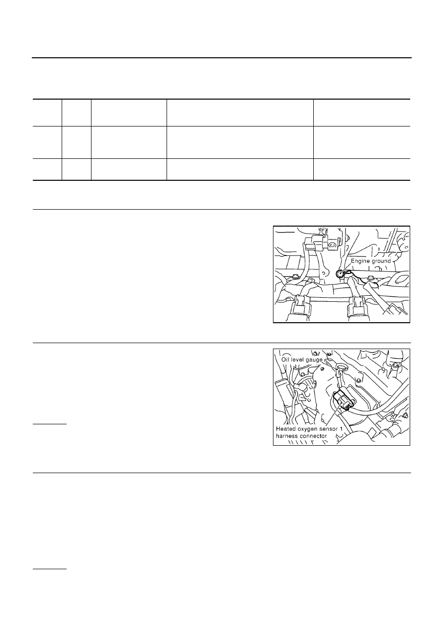
2.

Loosen and retighten engine ground screws.

>> GO TO 2.

2.

CHECK HO2S1 GROUND CIRCUIT FOR OPEN AND SHORT

1.

Disconnect heated oxygen sensor 1 harness connector.

2.

Disconnect ECM harness connector.

3.

Check harness continuity between ECM terminal 74 and HO2S1
terminal 3. Refer to Wiring Diagram.

4.

Also check harness for short to ground and short to power.

OK or NG

OK

>> GO TO 3.

NG

>> Repair open circuit or short to ground or short to power

in harness or connectors.

3.

CHECK HO2S1 INPUT SIGNAL CIRCUIT FOR OPEN AND SHORT

1.

Check harness continuity between ECM terminal 35 and HO2S1 terminal 2.
Refer to Wiring Diagram.

2.

Check harness continuity between ECM terminal 35 or HO2S1 terminal 2 and ground.
Refer to Wiring Diagram.

3.

Also check harness for short to power.

OK or NG

OK

>> GO TO 4.

NG

>> Repair open circuit or short to ground or short to power in harness or connectors.

TERMI-

NAL

NO.

WIRE

COLOR

ITEM

CONDITION

DATA (DC Voltage)

35

W

Heated oxygen sensor 1

[Engine is running]

Warm-up condition

Engine speed is 2,000 rpm.

0 - Approximately 1.0V
(Periodically change)

74

B

Sensors' ground
(Heated oxygen sensor)

[Engine is running]

Idle speed

Approximately 0V

MBIB0095E

Continuity should exist.

MBIB0091E

Continuity should exist.

Continuity should not exist.

DTC P0134 HO2S1 (M/T MODELS)

EC-235

[QG (WITH EURO-OBD)]

C

D

E

F

G

H

I

J

K

L

M

A

EC

4.

CHECK HEATED OXYGEN SENSOR 1

Refer to

EC-235, "Component Inspection"

.

OK or NG

OK

>> GO TO 5.

NG

>> Replace heated oxygen sensor 1.

5.

CHECK INTERMITTENT INCIDENT

Refer to

EC-138, "TROUBLE DIAGNOSIS FOR INTERMITTENT INCIDENT"

.

>> INSPECTION END

Component Inspection

EBS00QKE

HEATED OXYGEN SENSOR 1

With CONSULT-II

1.

Start engine and warm it up to normal operating temperature.

2.

Select “MANU TRIG” and adjust “TRIGGER POINT” to 100% in “DATA MONITOR” mode with CONSULT-
II.

3.

Select “HO2S1 (B1)” and “HO2S1 MNTR (B1)”.

4.

Hold engine speed at 2,000 rpm under no load during the follow-
ing steps.

5.

Touch “RECORD” on CONSULT-II screen.

6.

Check the following.

“HO2S1 MNTR (B1)” in “DATA MONITOR” mode changes
from “RICH” to “LEAN” to “RICH” more than 5 times in 10 sec-
onds.
5 times (cycles) are counted as shown at right.

“HO2S1 (B1)” voltage goes above 0.6V at least once.

“HO2S1 (B1)” voltage goes below 0.3V at least once.

“HO2S1 (B1)” voltage never exceeds 1.0V.

CAUTION:

Discard any heated oxygen sensor which has been dropped from a height of more than 0.5 m (19.7
in) onto a hard surface such as a concrete floor; use a new one.

SEF646Y

SEF217YA

SEF648Y

EC-236

[QG (WITH EURO-OBD)]

DTC P0134 HO2S1 (M/T MODELS)

Before installing new oxygen sensor, clean exhaust system threads using Oxygen Sensor Thread
Cleaner tool J-43897-18 or J-43897-12 and approved anti-seize lubricant.

Without CONSULT-II

1.

Start engine and warm it up to normal operating temperature.

2.

Set voltmeter probes between ECM terminal 35 (HO2S1 signal) and engine ground.

3.

Check the following with engine speed held at 2,000 rpm con-
stant under no load.

The voltage fluctuates between 0 to 0.3V and 0.6 to 1.0V
more than 5 times within 10 seconds.

The maximum voltage is over 0.6V at least one time.

The minimum voltage is below 0.3V at least one time.

The voltage never exceeds 1.0V.

1 time: 0 - 0.3V

0.6 - 1.0V

0 - 0.3V

2 times: 0 - 0.3V

0.6 - 1.0V

0 - 0.3V

0.6 - 1.0V

CAUTION:

Discard any heated oxygen sensor which has been dropped
from a height of more than 0.5 m (19.7 in) onto a hard surface such as a concrete floor; use a new
one.

Before installing new oxygen sensor, clean exhaust system threads using Oxygen Sensor Thread
Cleaner tool J-43897-18 or J-43897-12 and approved anti-seize lubricant.

Removal and Installation

EBS00QKF

HEATED OXYGEN SENSOR 1

Refer to

EM-21, "EXHAUST MANIFOLD AND CATALYTIC CONVERTER"

.

MBIB0018E

DTC P0134, P0154 HO2S1 (A/T MODELS)

EC-237

[QG (WITH EURO-OBD)]

C

D

E

F

G

H

I

J

K

L

M

A

EC

DTC P0134, P0154 HO2S1 (A/T MODELS)

PFP:22690

Component Description

EBS00QKG

The heated oxygen sensor 1 is placed into the exhaust manifold. It
detects the amount of oxygen in the exhaust gas compared to the
outside air. The heated oxygen sensor 1 has a closed-end tube
made of ceramic zirconia. The zirconia generates voltage from
approximately 1V in richer conditions to 0V in leaner conditions. The
heated oxygen sensor 1 signal is sent to the ECM. The ECM adjusts
the injection pulse duration to achieve the ideal air-fuel ratio. The
ideal air-fuel ratio occurs near the radical change from 1V to 0V.

CONSULT-II Reference Value in Data Monitor Mode

EBS00QKH

Specification data are reference values.

On Board Diagnosis Logic

EBS00QKI

Under the condition in which the heated oxygen sensor 1 signal is
not input, the ECM circuits will read a continuous approximately
0.3V. Therefore, for this diagnosis, the time that output voltage is
within 200 to 400 mV range is monitored, and the diagnosis checks
that this time is not inordinately long.

SEF463R

SEF288D

MONITOR ITEM

CONDITION

SPECIFICATION

HO2S1 (B1)
HO2S1 (B2)

Engine: After warming up

Maintaining engine speed at 2,000
rpm

0 - 0.3V

←→

Approx. 0.6 - 1.0V

HO2S1 MNTR (B1)
HO2S1 MNTR (B2)

LEAN

←→

RICH

Changes more than 5 times dur-
ing 10 seconds.

SEF237U

DTC No.

Trouble diagnosis name

DTC detecting condition

Possible cause

P0134
0134
(Bank 1)

Heated oxygen sensor 1
circuit no activity detected

The voltage from the sensor is constantly
approx. 0.3V.

Harness or connectors
(The sensor circuit is open or shorted.)

Heated oxygen sensor 1

P0154
0154
(Bank 2)


Content   ..  350  351  352  353   ..